
Owners manual
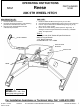
30160IN – 5JUN14 PCN3308 2014 CEQUENT™ PERFORMANCE PRODUCTS, INC PRINTED IN MEXICO
FOR KIT 30160
Assembly / Adjustment [1
st
TIME INSTALLATION ONLY]
TOOLS:
7/16”, 9/16” and 15/16" Socket & Open End Wrench
200 lb-ft Torque Wrench
1-1/2” Box End Wrench
Provided Wrench – PN 116596
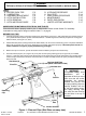
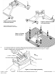
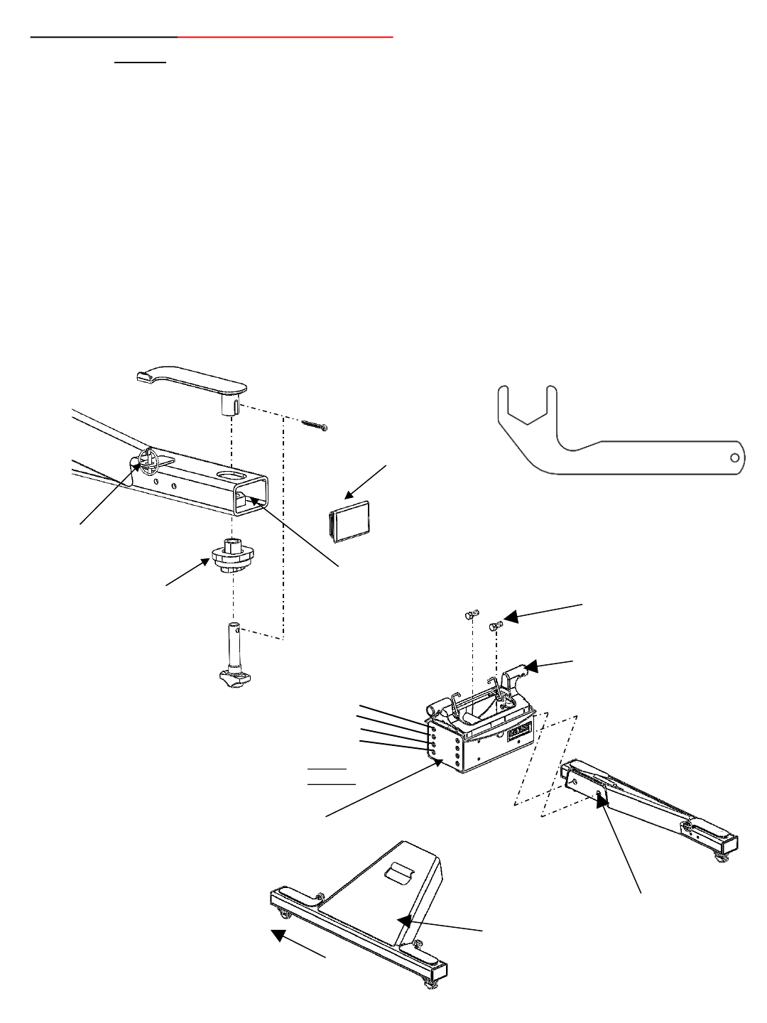
1. Check box for all components listed in Figure 6 and become familiar with component terminology. Center section, Base
Arches, and Anchor assemblies may be assembled upon packaging. If already assembled, start at Step 5. Use this
section if you need to adjust your assembly in the future.
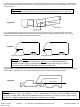
2. Loosely assemble the two base arches to the center section using 5/8-11 hex head bolts and lock washers (Figure 6).
NOTE A : Hole positions used in assembly will need to be chosen based on the head height measurements taken
previously (See Index F-8). Choose calculated height closest to one of the following height dimensions: 15-3/4”(2
nd
holes
down), 17”(3
rd
holes down), 18-1/4”. The top set of holes is not to be used on this hitch.
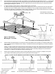
NOTE B : The fore/aft position of the head relative to the tow vehicle axle can be adjusted by 1-1/2” based on the position
of the center section (Figure 6). The center section should be positioned so that the posts are offset towards the front of the
vehicle. Please advise that the king pin should be 2” ahead of tow vehicle axle center to allow for proper towing clearances.
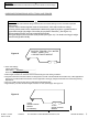
Figure 5: Anchor
Bushing Attachment
1” Jam Nut
Anchor Bushing
Figure 6 : Arch and
Center Assembly
Base Arch
Center Section
DO NOT USE
15-3/4”
17”
18-1/4”
5/8-11 Grade 8 Bolt(4)
5/8 Lock Washer(4)
HITCH
HEIGHT
Note offset of center section
Post toward the front of tow
vehicle
Front of Truck
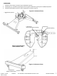
4
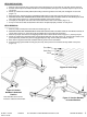
Lynch pin
Tube cover
Handle
Provided Wrench –
PN 116596
Note: The smaller tee pins
are positioned closer to the
front of the vehicle