COVER PAGE 30035 BASE RAIL MOUNTING KIT 10 BOLT RAIL KIT NOTE! If you have a newer model year truck you must go to one of our websites for the most recent updated instructions. www.ReeseProducts.com or www.Draw-Tite.com z 2006,2007,2008,2009,2010,2011,2012,2013, 2014 Cequent Performance Products, Inc. Made in China Cover Page 30035IN 10/20/2014 Rev.
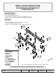
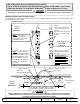
INSTALLATION INSTRUCTIONS 30035 BASE RAIL MOUNTING KIT 10 BOLT RAIL KIT DEALER/INSTALLER: (1) Provide this Manual to end user. (2) Physically demonstrate procedures in this Manual to end user. (3) Have end user demonstrate that he/she understands procedures. END USER: (1) Read and follow this Manual every time you use Hitch. (2) Save this Manual for future reference. (3) Pass on copies of Manual to any other user or owner of Hitch. 14 15 25 5 14 3 15 10 9 1 7 6 8 BASERAILS 1. LONG BRACKET 2.
GENERAL INSTRUCTIONS FOR 30035 BASE RAIL INSTALLATION TOOLS 3/16" drill 17/32" drill 1” drill (Some Dodge applications only) 3/4" Socket & Open End Wrench 100 lb-ft Torque Wrench "C" Clamps 1. The following instructions should be used to mount the fifth wheel. Care and attention to detail will ensure a quick quality installation. Check parts against parts list to become familiar with parts in kit. (See Fig. 1) 2.
9. Install mounting brackets onto carriage bolts with the long brackets on forward bolts and short brackets on rearward (long and short brackets can be interchanged as needed). Secure bolts through mounting brackets with serrated washers, lock washers, and hex nuts. Secure the other four bolts through the bed with flat washers, lock washers, and nuts. For Installation Assistance or Technical Help, Call 1-888-521-0510 10. Drill two holes in frame for each bracket.
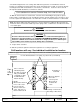
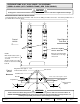
Chevy and GM 2011 and Newer, 2500 HD & 3500 HD Silverado and Sierra CAUTION! Read pages 2-3 of these instructions before starting installation. Failure to do so could result in significant vehicle damage! IMPORTANT NOTES FOR THIS INSTALLATION: ROW 4 ROW 3 Front of Vehicle ROW 2 ROW 1 1. Find parallel rows of bed sill spot welds in bed of truck. No drilling should be done in the ~4” between parallel rows of spot welds where the bed sill sits.
GM ‘99 Silverado, Sierra (not Sierra Classic) models. Chevy & GM ‘00 and newer 1500 Silverado Sierra. ‘00 to 10’ HD models, and ’04 & up 1500 Crew Cab with 5’8” bed (Reese SidewinderTM Pinbox required for 5’8” bed). CAUTION! Read pages 2-3 of these instructions before starting installation. Failure to do so could result in significant vehicle damage! IMPORTANT NOTES FOR THIS INSTALLATION: ROW 3 ROW 4 Front of Vehicle ROW 2 ROW 1 1. Find parallel rows of bed sill spot welds in bed of truck.
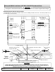
CHEVROLET/GMC 88-98 / 92-98 4-DOOR / ‘99 SILVERADO SIERRA CLASSIC (WITH TAPERED FRAME) (RED TURN SIGNALS) CAUTION! Read pages 2-3 of these instructions before starting installation. Failure to do so could result in significant vehicle damage! IMPORTANT NOTES FOR THIS INSTALLATION: ROW 4 ROW 3 ROW 2 ROW 1 1. Find parallel rows of bed sill spot welds in bed of truck. No drilling should be done in the ~4” between parallel rows of spot welds where the bed sill sits.
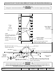
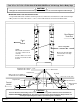
Chevrolet 73 to 87 / 73 to 92 4-door (GMC) (34” Straight, with Outside Shock Absorbers) CAUTION! Front of Vehicle ROW 4 ROW 3 ROW 2 ROW 1 Read pages 2-3 of these instructions before starting installation. Failure to do so could result in significant vehicle damage! Rear Edge of Truck Bed Drill through bed and truck frame NOTE: Must install center bolt in one of the center holes in each rail. Check to make sure center bolt does not interfere with bed sill.
Chevrolet 73 to 87 / 73 to 92 4-door (GMC) (34” Straight, with Inside Shock Absorbers) CAUTION! ROW 4 ROW 3 ROW 2 ROW 1 Read pages 2-3 of these instructions before starting installation. Failure to do so could result in significant vehicle damage! Front of Vehicle Rear Edge of Truck Bed NOTE: Must install center bolt in one of the center holes in each rail. Check to make sure center bolt does not interfere with bed sill.
Ford ‘97 to ’03 F-150 & F-250 8500 GVW AND UNDER and ’04 Heritage Series Body Style CAUTION! Read pages 2-3 of these instructions before starting installation. Failure to do so could result in significant vehicle damage! IMPORTANT NOTES FOR THIS INSTALLATION: 1. Long and Short Brackets on Driver’s Side may need to be switched to avoid interference with exhaust hanger. ROW 4 ROW 3 ROW 2 ROW 1 2. May need to move base rail location +/- 1/2” to ensure frame brackets do not interfere with bed sills.
FORD F-150 & F-250 THROUGH ’96 / ‘97 F-250 OVER 8500 GVW, F350 THROUGH ’97 / 1999 & NEWER F-250 / F-350 & F-450 SUPERDUTY PICKUPS (Not Cab-On-Chassis) CAUTION! Read pages 2-3 of these instructions before starting installation. Failure to do so could result in significant vehicle damage! IMPORTANT NOTES FOR THIS INSTALLATION: 1. On short bed vehicles, attach Driver’s Side forward bracket on Row 2 to avoid interference with fuel lines. 2.
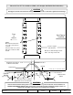
DODGE (RAM) ‘02-08’ 1500 / ‘03-12’ 2500 WITHOUT OVERLOAD BRACKETS (‘03-12’ 2500 WITH OVERLOAD AND 3500 REQUIRED BRACKET KIT 58186, See page 18) CAUTION! Read pages 2-3 of these instructions before starting installation. Failure to do so could result in significant vehicle damage! Vehicle ROW 4 ROW 3 ROW 2 ROW 1 IMPORTANT NOTES FOR THIS INSTALLATION: 1. Tube spacer and 4 1/2” carriage bolt used to attach through rearward Bed Sill (Row 3). 2.
2013 MODEL YEAR RAM 2500 HD (Dodge/Chrysler) (without overload brackets) CAUTION! Read pages 2-3 of these instructions before starting installation. Failure to do so could result in significant vehicle damage! 5. *Due to tubular frames having thinner walls than previous C channel frames, extra caution needs to be used when mounting with the optional welding. Drill through Bed Sill with 17/32” drill. Open up hole through truck bed only with 1” dia. drill.
DODGE ‘94 to ‘01 1500 / ‘94 to ‘02 2500/3500 (FULL SIZE, SHORT AND LONG BOX) CAUTION! Read pages 2-3 of these instructions before starting installation. Failure to do so could result in significant vehicle damage! ROW 4 ROW 3 ROW 2 ROW 1 IMPORTANT NOTES FOR THIS INSTALLATION: 1. It is very important that brackets in Row 2 are against forward side of bed sill as shown below. Due to dimensional instability in bed sill placement with the Dodge truck, interference could result when drilling in Rows 3 or 4.
DODGE THROUGH 93 (FULL SIZE) CAUTION! Read pages 2-3 of these instructions before starting installation. Failure to do so could result in significant vehicle damage! IMPORTANT NOTES FOR THIS INSTALLATION: ROW 4 ROW 3 ROW 2 ROW 1 1. May need to move base rail location +/- 1/2” to ensure frame brackets do not interfere with bed sills. Rear Edge of Truck Bed Front of Vehicle 29-5/8” Long Box and Short Box NOTE: Must install center bolt in one of the center holes in each rail.
DODGE ’94 to 2004 DAKOTA CAUTION! Read pages 2-3 of these instructions before starting installation. Failure to do so could result in significant vehicle damage! IMPORTANT NOTES FOR THIS INSTALLATION: 1. Find parallel rows of bed sill spot welds in bed of truck. No drilling should be done in the ~4” between parallel rows of spot welds where the bed sill sits. ROW 4 ROW 3 Cut Off 1" ROW 2 ROW 1 2. Cut 1” from top flange of brackets. Under bed, mount brackets with flanges facing out. 3.
TOYOTA TUNDRA 2000 to 2006 (STANDARD CAB LONG BOX ONLY) CAUTION! Read pages 2-3 of these instructions before starting installation. Failure to do so could result in significant vehicle damage! ROW 4 ROW 3 ROW 2 ROW 1 NOTE: For Toyota Tundra application, part #58197 spacer kit is required. Stack (1) 3/16” and (1) 5/16” thick slotted spacer to avoid crushing of truck bed. Front of Vehicle Rear Edge of Truck Bed NOTE: Must install center bolt in one of the center holes in each rail.
2007 And Newer Toyota Tundra 6.5’ & 8’ Beds – requires Service Kit 58309 (Crewmax 5.5’ Bed requires Reese SidewinderTM Pinbox) CAUTION! Read pages 2-3 of these instructions before starting installation. Failure to do so could result in significant vehicle damage! ROW 4 ROW 3 ROW 2 ROW 1 IMPORTANT NOTES FOR THIS INSTALLATION: 1. Use the 58309 service kit together with the 30035 mounting kit. Read p. 1-3 of the 30035 instruction for general information. 2.
REQUIRED ADAPTOR BRACKETS 2004 - 2014 FORD F-150 – REGULAR, SUPERCAB & SUPER CREW– SEE 58426N FOR DETAILS (5-1/2’ Bed Requires Reese SidewinderTM Pinbox) 2015 & Up FORD F-150 – REGULAR, SUPERCAB & SUPER CREW– SEE 58545N FOR DETAILS (5-1/2’ Bed Requires Reese SidewinderTM Pinbox) 2003 – 2012 DODGE(RAM) 2500/3500 with Overload Brackets – REGULAR, QUAD & CREW– SEE 58186N FOR DETAILS (5-1/2’ Bed Requires Reese SidewinderTM Pinbox) 2009 & Up DODGE(RAM) 1500 – REGULAR, QUAD & CREW– SEE 58386N FOR DETAILS (5-1/2’
NOTES 10 YEAR LIMITED WARRANTY CEQUENT PERFORMACE PRODUCTS, INC. warrants its Fifth Wheel Hitch Mounting Kits from date of purchase against defects in material and workmanship under normal use and service, ordinary wear and tear excepted, for 10 years of ownership to the original consumer purchaser when a CEQUENT PERFORMACE PRODUCTS, INC. mounting kit is used. CEQUENT PERFORMACE PRODUCTS, INC.