
Instructions


51
11. Possible settings on the vehicle
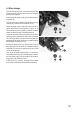
a) Adjusting the wheel camber
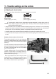
The wheel camber refers to the tendency of the wheel plane relative to the vertical.
Negative camber Positive camber
(wheel top edges point inward) (wheel top edges point outward)
Thesettingofthewheelsinthetwoimagesabovehasbeenexaggerated,inordertoshowyouthedif-
ferencebetweenanegativeandapositivecamber.Obviouslysuchanextremesettingassettingforthe
model vehicle should not be done!
• Anegativecamberonthefrontwheelsincreasesthelateralguidingforcesofthewheelsincurves;thesteering
respondsmoredirectly,thesteeringforcesarelower.Simultaneously,thewheelispressedintheaxialdirectionto
theaxlejournal.Thus,theaxialbearingclearanceiscompensated,thedrivingbehaviourisquiet.
• A negative camber on the rear wheels reduces the tendency of the vehicle rear to break loose in curves.
• On the other hand, the setting of a positive camber reduces the lateral guiding forces of the tires and should not
be used.
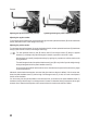
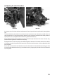
Adjusting the wheel camber on the front axle:
The so-called „pivot-ball“ on the front axle suspension
consistsofaspeciallyshapedaxlejournal,twospherical
headscrews(AandB)andtwoexternalplasticheadless
screws (C).
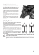
For setting the camber, the spherical head screws (A) and
(B)mustbeadjustedwithasmall2,5mmhexagonwrench
(D), which is inserted through the hole of the headless
screw(C)(seenextpage).
The plastic headless screws (C) can be tightened or loo-
senedwitha slightly larger5mm hexagonwrench(E).
However, they serve only to x the axle journal onthe
spherical head screws (A) and (B).
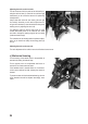
Never apply excessive force when turning the plastic
headless screws (C), otherwise the suspension cannot
move freely. However, the headless screws (C) may not
besittooloose,otherwisetheaxlejournalwobbles.