Operating Instructions 10-channel remote control “HT-10”, 2.4 GHz Item No.
Table of Contents Page 1. Introduction...........................................................................................................................................................3 2. Explanation of Symbols........................................................................................................................................3 3. Intended Use.......................................................................................................................................
1. Introduction Dear Customer, thank you for purchasing this product. This product complies with the statutory national and European requirements. To maintain this status and to ensure safe operation, you as the user must observe these operating instructions! These operating instructions are part of this product. They contain important notes on commissioning and handling. Also consider this if you pass on the product to any third party.
3. Intended Use The 10-channel remote control "HT-10" is solely designed for private use in the field of model construction and the operating times associated with it. This system is not suitable for industrial use, such as controlling machines or equipment. Any use other than that described above can damage the product and involves additional risks such as short circuit, fire, electric shock, etc.
. Scope of Delivery • Remote control transmitter • Remote control receiver • Binding plug • Latching bracket with screws • Operating instructions on CD Current operating instructions Download the current operating instructions via the link www.conrad.com/downloads or scan the QR code displayed. Observe the instructions on the website. 6. Safety Notes In case of damage caused by non-compliance with these operating instructions, the warranty/ guarantee will expire.
• Please check the functional safety of your model and of the remote control system each time before you use the model. Watch out for any visible damage such as defective plug connections or damaged cables. All movable parts on the model have to be running smoothly. However, there must be no tolerance or 'play' in the bearing.
. Battery and Rechargeable Battery Notes Although use of batteries and rechargeable batteries in everyday life is a matter of course today, there are many dangers and problems. Therefore, always observe the following information and safety notes in handling of batteries and rechargeable batteries. • Keep batteries/rechargeable batteries out of the reach of children. • Do not leave any batteries/rechargeable batteries lying around openly. There is a risk of batteries being swallowed by children or pets.
. Charging Rechargeable Batteries If you use rechargeable batteries for power supply of the receiver, they are usually flat at delivery and must be charged. Observe: Before a rechargeable battery reaches maximum capacity, several complete discharge and charge cycles are necessary. Always discharge the rechargeable battery at regular intervals, since charging a "half-full" rechargeable battery several times can cause a so-called lazy battery effect.
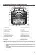
. Operating Elements of the Transmitter Figure 1 1 Transmitter aerial 11 Reverse switch for channel 1 - 4 2 Dial switch for channel 8 12 Mixer switch 3 Carrying handle 13 Binding button 4 Switch for channel 9 14 Trimming button for channel 4 5 Switch for channel 10 15 Control stick for channel 3 and 4 6 Trimming button for channel 2 16 Trimming button for channel 3 7 Control stick for channel 1 and 2 17 Switching button for channel 5 8 Trimming button for channel 1 18 Switch
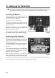
. Setting up the Transmitter In the further course of these instructions, figures in the text always refer to the adjacent figure or the figures within the section. References to other figures are indicated with the corresponding figure number. a) Inserting the Batteries For the power supply of the transmitter you will need 4 alkaline batteries (e.g. Conrad item no. 652507, pack of 4, order 1x) of the size AA/mignon.
c) Setting the Control Stick Length You can adjust the length of the control sticks, depending on your steering habits. To do so simply hold the bottom part of the grip (1) and turn the upper part (2) up anti-clockwise. You can now set the length of the control lever by turning the bottom part of the grip. Finally, tighten the upper part of the grip back up.
11. Setting up the Receiver a) Connecting the Receiver The receiver offers connection options for up to 10 servos (channels 1 to 10 correspond to the receiver outputs "CH1" to "CH10"). The servos can also be replaced by motor/speed controllers or switching elements.
When using servos with high power demand, we recommend to always use a receiver battery pack. The connections are designed for Futaba plug connectors. If required, you can also easily use JR plugs or plug connectors of the same build. Important! When connecting servos and speed controllers, always make sure of correct polarity of the plug connectors.
b) Mounting the Receiver Installation of the receiver depends on the model. For this reason, you should always follow the recommendations of the model manufacturer regarding the installation. Regardless of the model, you should always try to install the receiver so that it is protected from dust, dirt, moisture, heat and vibration in the best possible way. Keep enough distance from motors and electronic flight or speed controllers.
12. Installing the Servos The installation of a servo (1) always depends on the particular model used. Detailed information on this can be found in the construction documents of the model. Generally, however, try screwing in the servos in a vibration-dampened manner. This is why rubber bushings (2) with metal sleeves (3) are usually included with the servos. When linkages are stiff, the servos cannot assume the required positions.
13. Setting the Trim The trim mostly serves to correct the slight inclination of the servo levers for channels 1 to 4 due to the interlock and the connected irregular control movements. Additionally, there is the option to adjust the model in operation precisely, e.g. if it is not flying straight although the control lever is in the middle position.
14. Checking the Servo Directions of Travel For function, driving or ship models, you can individually specify the driving and steering functions of the control levers, since both control levers are returned to the middle position by spring force. For flight or helicopter models, it is best to comply with the above control lever functions for channels 1 to 4.
15. Switching the Servo Directions of Travel If the movement directions of the servos or the speed controller function at the receiver outputs "CH1" to "CH4" are not as required, you can switch the running direction of the servos or the speed controller function in the transmitter with the reverse switches (also see figure 1, item 11).
16. Conversion of the Control Lever Functions If you want to control a motor-powered flight model with your "HT-10" remote control, the left control lever must not return to the middle position on its own at forward or reveres movement (throttle/pitch function). It must remain in the position into which it was last moved. For this, the return mechanic must be deactivated and the control lever movement friction must be enlarged.
17. Changing the Control Lever Allocation If you do not want to operate your motor or helicopter model by controlling the throttle/pitch function with the left control lever (mode II) as intended ex works, but with the right control lever (mode I), the transmitter can be adjusted accordingly. Important! First deactivate the return mechanics of the left (the right when viewed from the rear) control lever mechanics as described in the previous section.
18. Mixer Function The remote control "HT-10" has a mixer function that can be activated with the mixer switch (also see figure 1, item 12). When the slider is in the bottom position, regular operation without mixer function is active. If the slider is pushed up, channel 1 "CH1" and channel 2 "CH2" will be mixed. Use of the mixer in a plane model: For a delta plane model with triangular wing, the ailerons also have to perform the elevator function. For this reason, such models require a mixer.
Figure 13 22
Use of the mixer in a crawler: In a crawler where every chain is controlled via a dedicated motor with speed controller, channel 2 "CH2" and channel 3 "CH3" can be used for driving. The control then takes place with the two control levers and the mixing function can be switched off. When both control levers are in the centre positions, the vehicle is standing still (see upper illustration in figure 14). If connected correctly, the two drive chains run as the two control levers at the transmitter are moved.
If you want to control only using one control lever, the two speed controllers for the left and right chains must be connected to channel 1 "CH1" and channel 2 "CH2". When the mixer has been activated, the model must react according to figure 15. The left control lever then can be used for other functions, such as when lifting and lowering a clearing shield.
19. Switching the Digital Code The remote control transmitter enables you to control receivers with the digital code "AFHDS" and "AFHDS 2A". Ex works, the transmitter is set to the enclosed "AFHDS 2A" encoded receiver. If you want to operate a REELY receiver with the digital code "AFHDS", the transmitter must be switched first and then the receiver must be bound to the transmitter (see following chapter). To switch the digital code at the transmitter, proceed as follows: Switch off the transmitter.
20. Binding Function To enable transmitter and receiver to work together, they must be bound by the same digital code. In the delivery state, transmitter and receiver are aligned with each other and can be used at once. The binding settings must be renewed mainly after a replacement of the transmitter or receiver or to remove any interferences. Before you can bind the receiver to the transmitter, check if the transmitter works in the right digital code (see previous chapter).
21. Simulator Function, Student Transmitter Function If required, you can also use the transmitter at the PC for simulations or games. In this case, you will require the optional USB cable (Conrad item no. 517956) and suitable computer software (e.g. flight simulation games, etc.). The USB cable is connected to the PS2 interface socket (1) at the rear of the transmitter. At correct connection and proper installation, the activated transmitter is recognised by the operating system (e.g.
23. Troubleshooting Problem Remedy Transmitter doesn’t respond • Check the batteries in the transmitter. • Check the polarity of the batteries. • Check the battery contacts of the remote control. • Check the on/off switch. The servos do not respond • Check the batteries in the receiver. • Test the switch cable. • Test the BEC function of the controller. • Check the polarity of the servo connector. • Check the digital coding of the transmitter. • Perform binding.
24. Disposal a) Product Electronic devices are recyclable and should not be disposed of in household waste. Dispose of the product according to the applicable statutory provisions at the end of its service life. Remove any inserted batteries/rechargeable batteries and dispose of them separately from the product. b) Batteries/Rechargeable Batteries You as the end user are required by law (Battery Ordinance) to return all used batteries/rechargeable batteries.
26. Technical Data a) Transmitter Frequency range ����������������������������������2.
This is a publication by Conrad Electronic SE, Klaus-Conrad-Str. 1, D-92240 Hirschau (www.conrad.com). All rights including translation reserved. Reproduction by any method, e.g. photocopy, microfilming, or the capture in electronic data processing systems require the prior written approval by the editor. Reprinting, also in part, is prohibited. This publication represent the technical status at the time of printing. Copyright 2017 by Conrad Electronic SE.