
User manual


13
11. Starting up the receiver
11.1 Receiver connection
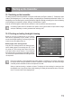
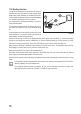
Thereceiver offersconnection optionsfor upto fourservos (CH1, CH2,CH3, CH4)and areceiver battery pack
(BIND/VCC).
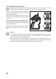
Figure5ashowsaconnectionchartforamodelwithexternalreceiverpowersupply(gure5a,item1),asitiscom-
mon,e.g,foracombustionmodel.
Figure 5b shows a connection chart for an electrically powered model in which the speed controller has an integrated
BEC(BECisareceiverpowersupplyintegratedintothespeedcontroller).Thedrivingbattery(gure5b,item1)is
connectedtothespeedcontroller(gure5b,item2)here.TheBECintegratedinthespeedcontrollersuppliesthe
entirereceiversystemwithpowerthroughtheconnectionoftheservoplugfromthespeedcontrollertoCH2.
IfthespeedcontrolleruseddoesnothaveanyintegratedBEC,thereceiversystemmustbeproducedwithanexternal
receiverpowersupply.Usegure5aasreference.Inthiscase,onlytheservoServo2(CH2)needstobereplaced
by the speed controller.
IfanelectronicspeedcontrollerwithintegratedBECisusedinamodel,noexternalpowersupplymustbe
connectedtothereceiver,sincethismaydestroythespeedcontroller.TheBECmaybedisconnectedfrom
thereceiversystemforuseofexternalreceiverpowersuppliesifyouseparatethemiddle,redwireatthe
servo plug of the speed controller and insulated it.
Ifnecessary,youcanconnectanadditionalservotoreceiveroutputCH3andCH4inadditiontothesteeringservo
onreceiveroutput“CH1”andthethrottleservo/speedcontrolleronreceiveroutput“CH2”.Theseservoscanbeused
for various additional functions.
Withaelectronicmodelwithamechanicaldriveregulator,abatteryboxoraseparatereceiverbatterypackisrequi-
red for the power supply of the receiver in all cases. The power supply connection mounted to the mechanical drive
regulatormaynotbeusedsincethevoltageattheplugof7.2V(fora6celldrivebattery)istoohighforthereceiver
and the connected servos.
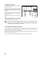
Pay attention when connecting servos to always ensure the correct poling of the plug connector. The plugged contact
fortheimpulsecable(yellow,whiteororangeaccordingtomanufacturer)mustbeconnectedtotheinner(left)pin
contact.Thepluggedcontactfortheminuscable(blackorbrownaccordingtomanufacturer)mustbeconnectedto
theouter(right)pincontact.
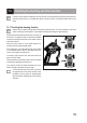
Switchthetransmitteronandthenswitchthereceiveron.IftheBindingfunctioniscorrect,theredcontrolLEDonthe
receiver will light up. Check the correct functionality of the receiver and then switch it back off.
IftheLEDsinthereceiverdonotlightuportheconnectedservosdonotreacttotheremotecontrolsignals,
the Binding function must be carried out. More information can be found in the later Chapter “Binding func-
tion”.