
User manual

17
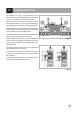
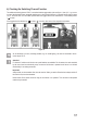
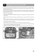
b) Checking the Switching Channel Function
The additional switching channel "CH 5" is controlled with the toggle switch (also see gure 1, item 4). If, e.g., a servo
to control landing/spoiler aps, retractable landing gear or other special functions is connected at the receiver output
"CH 5", the servo lever is in the middle position when the toggle switch at the transmitter is in the middle position
( ) as well.
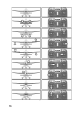
If the toggle switch is switched up ( ) or down ( ), the servo lever runs to the respective end position.
Figure 11
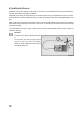
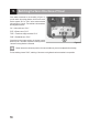
As an alternative to a servo, switching modules, e.g. for model lighting, can also be connected to the re-
ceiver output "CH 5".
Attention!
For channel 5, neither a trim function nor a path limitation are available. For this reason, the rods controlled
by the servo must be mechanically set up so that the full function is present but the servo is not limited
mechanically in its rotating movement.
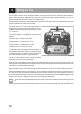
Important!
Always switch on the transmitter rst, then the receiver. When you switch off the devices, always switch off
the receiver rst, then the transmitter.
Never switch off the remote control as long as the receiver is in operation. This can lead to unexpected
reactions by the model!