
User manual

13
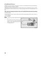
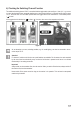
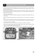
12. Installing the Servos
The installation of a servo (1) always depends on the
particular model used. Detailed information on this can be
found in the construction documents of the model.
Generally, however, try screwing in the servos in a vibra-
tion-dampened manner. This is why rubber bushings (2)
with metal sleeves (3) are usually included with the servos.
When linkages are stiff, the servos cannot assume the re-
quired positions. This causes higher power consumption
and the model cannot be controlled properly.
The linkages must work as smoothly as possible without
having any play in the bearings or deections.
Before installing the servo lever, take the transmitter and
then the receiver into operation and check the trim at the
remote control transmitter for correct middle position (see
following chapter).
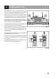
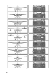
Then always mount the servo stick at a 90° angle to the
linkage rods (see gure 8, sketch A).
The servo lever is at an angle to the linkage rod (see gure
8, sketch B), the control paths of the two control directions
will be unequal.
A slight mechanical inclination due to interlock of the servo
levers may be corrected with the trim later.
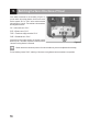
Figure 7
Figure 8