
User manual

11
11. Setting up the Receiver
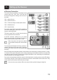
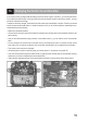
a) Receiver Connection
The receiver offers the possibility of connecting 5 servos
(receiver output "CH1", "CH2", "CH3", "CH4" and "CH5")
that are later assigned the following control functions in
the model:
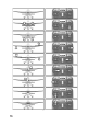
"CH1" = Aileron/roll servo
"CH2" = Elevator/nod servo
"CH3" = Throttle servo/ight controller/speed controller
"CH4" = Rudder/tail servo
"CH5" = Special function
The receiver output "CH5" can be used for special func-
tions such as landing aps, spoiler aps, retractable land-
ing gear or switching functions.
The receiver output "CH6" is not used, since the transmit-
ter only transmits the rst ve channels.
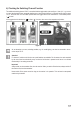
At the "BAT" connection, a battery box (1) or a receiver
battery with switch cable (2) is connected if no ight con-
troller or speed controller with BEC switch is used.
When using servos with high power demand,
we recommend to always use a receiver battery
pack.
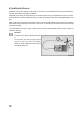
The connections are designed for JR plug connectors. If
required, Futaba plugs can be used as well, if a key le or
a sharp knife is used to remove the narrow guide bridge
at the plug.
When connecting servos and speed controllers, always make sure of correct polarity of the plug connectors. The plug-
in connection for the positive lead (yellow, white or orange, depending on the manufacturer) must be connected to the
inner (left) pin contact. The plug-in connection for the negative lead (black or brown, depending on the manufacturer)
must be connected to the outer (right) pin contact.
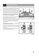
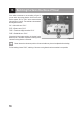
First, switch on the transmitter and then the receiver. If the binding function is working correctly, the red LED indicator
in the receiver (see gure 5, item 3) lights up and the ve servos react to the movements of the control levers. Verify
correct receiver function and then switch the receiver off again.
If the servos do not react and the LEDs in the receiver do ash, perform binding (see chapter 20).
Figure 5