Operating instructions Remote Control "HT-5", 2.4 GHz Item No.
Table of Contents 1. 2. 3. 4. 5. 6. 7. 8. 9. 10. 11. 12. 13. 14. 15. 16. 17. 18. 19. 20. 21. 22. 23. 24. 25. 26. 2 Page Introduction...........................................................................................................................................................3 Explanation of Symbols........................................................................................................................................3 Intended Use........................................
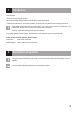
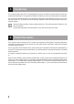
1. Introduction Dear Customer, Thank you for purchasing this product. This product complies with the statutory national and European requirements. To maintain this status and to ensure safe operation, you as the user must observe these operating instructions! These operating instructions are part of this product. They contain important notes on commissioning and handling. Also consider this if you pass on the product to any third party.
3. Intended Use The 5-channel remote control "HT-5" is solely designed for private use in the field of model construction and the operating times associated with it. This system is not suitable for industrial use, such as controlling machines or equipment. Any use other than that described above can damage the product and involves additional risks such as short circuit, fire, electric shock, etc.
. Scope of Delivery • Remote control transmitter • Remote control receiver • Binding plug • Operating instructions on CD Current operating instructions: 1. Open www.conrad.com/downloads in a browser or scan the QR-code shown on the right. 2. Select the document type and language, and then enter the corresponding order number in the search field. After searching starts, you can download the documents found. 6.
• Please check the functional safety of your model and of the remote control system each time before you use the model. Watch out for any visible damage such as defective plug connections or damaged cables. All movable parts on the model have to be running smoothly. However, there must be no tolerance or 'play' in the bearing.
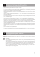
. Battery and Rechargeable Battery Notes • Keep batteries/rechargeable batteries out of the reach of children. • Do not leave any batteries/rechargeable batteries lying around openly. There is a risk of batteries being swallowed by children or pets. If swallowed, consult a doctor immediately! • Batteries/rechargeable batteries must never be short-circuited, disassembled or thrown into fire.
9.
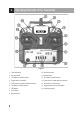
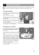
10. Setting up the Transmitter In the further course of these instructions, figures in the text always refer to the adjacent figure or the figures within the section. References to other figures are indicated with the corresponding figure number. a) Inserting the Batteries For the power supply of the transmitter you will need 4 alkaline batteries (e.g. item no. 652507, pack of 4, order 1) of the size AA/mignon.
c) Setting the Control Lever Length You can adjust the length of the control levers, depending on your steering habits. To do so simply hold the bottom part of the grip (1) and turn the upper part (2) up anti-clockwise. You can now set the length of the control lever by turning the bottom part of the grip. Finally, tighten the upper part of the grip back up.
. Setting up the Receiver a) Receiver Connection The receiver offers the possibility of connecting 5 servos (receiver output "CH1", "CH2", "CH3", "CH4" and "CH5") that are later assigned the following control functions in the model: "CH1" = Aileron/roll servo "CH2" = Elevator/nod servo "CH3" = Throttle servo/flight controller/speed controller "CH4" = Rudder/tail servo "CH5" = Special function The receiver output "CH5" can be used for special functions such as landing flaps, spoiler flaps, retractable la
b) Installing the Receiver Installation of the receiver depends on the model. For this reason, you should always follow the recommendations of the model manufacturer regarding the installation. Regardless of the model, you should always try to install the receiver so that it is protected from dust, dirt, moisture, heat and vibration in the best possible way and is not located in the direct proximity of the rechargeable battery/motor lines.
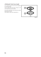
12. Installing the Servos The installation of a servo (1) always depends on the particular model used. Detailed information on this can be found in the construction documents of the model. Generally, however, try screwing in the servos in a vibration-dampened manner. This is why rubber bushings (2) with metal sleeves (3) are usually included with the servos. When linkages are stiff, the servos cannot assume the required positions.
13. Setting the Trim The trim mostly serves to correct the slight inclination of the servo levers due to the interlock and the connected irregular control movements. Additionally, there is the option to adjust the model in operation precisely, e.g. if it is not flying straight although the control lever is in the middle position. Then the linkage or rudder rods must be adjusted so that the trim has its original value (90°-range between servo lever and rods) again and the model still runs straight.
14. Checking the Servo Directions of Travel a) Checking the Control Lever Functions For figure 10 for this section, see the next page. Connect the servos inserted in the model to the receiver. Pay attention to the assignment of the receiver outputs as described above. If your model has two aileron servos, there is the possibility of operating both servos with a V-cable at the receiver output "CH1". Take the transmitter into operation, then the receiver.
Figure 10 16
b) Checking the Switching Channel Function The additional switching channel "CH 5" is controlled with the toggle switch (also see figure 1, item 4). If, e.g., a servo to control landing/spoiler flaps, retractable landing gear or other special functions is connected at the receiver output "CH 5", the servo lever is in the middle position when the toggle switch at the transmitter is in the middle position ( ) as well.
15. Switching the Servo Directions of Travel If the rudder movements are not according to figure 10, you can switch the running direction of the servos at the receiver outputs "CH1" to "CH 4" at the reverse switches (also see figure 1, item 9).
16. Changing the Control Lever Allocation If you want to control your flight model according to the chart shown in figure 10 (mode II), you can skip this section. If you prefer the throttle function on the right control lever and the elevator function on the left one (mode I), you may convert the transmitter accordingly. To make the necessary changes, some experience with remote control transmitters is required.
17. Delta Mixer For figure 14 for this section, see the next page. The remote control "HT-5" has a delta mixer that can be activated with the mixer switch (also see figure 1, item 10). When the slider is in the bottom position, regular operation without mixer function is active. When the slider is put up, the delta mixer is activated. For a delta plane model with triangular wing, the ailerons also have to perform the elevator function.
Figure 14 21
18. Servo Path Limitation Use the servo path limitation or the dual rate function to reduce the servo deflections of channels 1, 2 and 4 from 100% to 60%. You can use this function to simply and easily reduce the reaction sensitivity of a model which reacts too aggressively at full extension. Especially when a model is used for the first time, it might not yet be clear how sensitively it responds to the control commands. Therefore it is a proven method to reduce large rudder deflections during flight.
19. Switching the Digital Code The remote control transmitter enables you to control receivers with the digital code "AFHDS" and "AFHDS 2A". Ex works, the transmitter is set to the enclosed "AFHDS 2A" encoded receiver. If you want to operate a Reely-receiver with the digital code "AFHDS", the transmitter must be switched first and then the receiver must be newly bound to the transmitter (see following chapter).
20. Binding Function To enable transmitter and receiver to work together, they must be bound by the same digital code. In the delivery state, transmitter and receiver are aligned with each other and can be used at once. The binding settings must be renewed mainly after a replacement of the transmitter or receiver or to remove any interferences. Before you can bind the receiver to the transmitter, check if the transmitter works in the right digital code (see previous chapter).
21. Simulator Function, Student Transmitter Function If required, you can also use the transmitter at the PC for simulations or games. In this case, you will require the optional USB cable (Conrad item no. 517956) and suitable computer software (e.g. flight simulation games, etc.). The USB cable is connected to the PS2 interface socket (16) at the rear of the transmitter. At correct connection and proper installation, the activated transmitter is recognised by the operating system (e.g.
24. Disposal a) General Information Electronic devices are recyclable and should not be disposed of in household waste. At the end of its service life, dispose of the product according to the relevant statutory regulations. Remove any inserted batteries/rechargeable batteries and dispose of them separately from the product. b) Batteries and Rechargeable Batteries You as the end user are required by law (Battery Ordinance) to return all used batteries/rechargeable batteries.
25. Troubleshooting Even though the remote control system was built to the state of the art, there can still be interference or faults. For this reason, we would like to give you some information on how to deal with possible problems. Problem Remedy Transmitter doesn’t respond • Check the batteries in the transmitter. • Check the polarity of the batteries. • Check the battery contacts of the remote control. • Check the on/off switch. The servos do not respond • Check the transmitter function.
26. Technical Data a) Transmitter Frequency range ����������������������������������2.
Legal Notice This is a publication by Conrad Electronic SE, Klaus-Conrad-Str. 1, D-92240 Hirschau (www.conrad.com). All rights including translation reserved. Reproduction by any method, e.g. photocopy, microfilming, or the capture in electronic data processing systems require the prior written approval by the editor. Reprinting, also in part, is prohibited. This publication represent the technical status at the time of printing. © Copyright 2016 by Conrad Electronic SE.