
Manual


Operating Instructions
Reelcraft Industries, Inc. • 2842 E Business Hwy 30, Columbia City, IN 46725
Ph: 800-444-3134 / 260-248-8188 • Fax: 800-444-4587 / 260-248-2605
Customer Service: 855-634-9109 • reelcraft@reelcraft.com • www.reelcraft.com
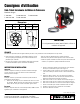
Safe-T-Reel Power Cable Reels
Model Numbers:
T-1535-003 T-1535-083-100 T-1535-103-200
T-1535-123-100 T-1535-123-200
Read this manual carefully before installing, operating or
servicing this equipment.
IMPORTANT
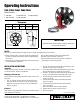
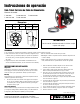
Four 1/2” diameter mounting holes
Dimensions
A B C D E
19” 18” 6” 6 1/2” 15 3/4”
Form# 1106-801 Rev: 3/2014
A
B E
C
D
•Beforeconnectingreeltosupplylineensurethatvoltage/amper-
age does not exceed maximum rated working voltage/amperage
rating of reel.
•Ensurethatreelisproperlyinstalledbeforeconnectingtosupply
line (see installation instructions).
•Donotwearloosefittingclothingwhileoperatingreel.
•Beawareofotherpersonnelinworkarea.
•Treatandrespectthereelasanyotherpieceofmachinery,
observing all common safety practices.
SAFETY
Personal injury and/or equipment damage may result if proper safety precautions are not observed.
INSTALLATION INSTRUCTIONS
Inspection
Unpackandinspectreelfordamage.Turnthereelbyhandtocheck
for smooth operation. Check for completeness.
Mounting of the hose reel
Note:Ensurethatonlyaqualifiedelectricianinstalls/servicesthis
equipment.
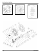
1. Four 1/2” diameter mounting holes are located at the base
of the reel. Mount reel using four (customer supplied) bolts;
tightening them securely to ensure a solid, rigid attachment
(figure 1 on page 2).
Electrical
Note:ObserveanyapplicableNEC,OSHAandlocalelectricalcodes
when installing this equipment.
1. Remove spool cover by loosening the six self-tapping screws
that hold it in place (figure 2 on page 2).
2. Feed output cable through hole located within the spool. Pull
enough cable through for roughly half an inner wrap.
3. Remove 6” of output cable outer jacket and add fork terminals
to ends. Locate terminal block assemblies behind cover.
4. Connect black output cable to terminal block assembly
(figure 3 on page 2).
5. Connect green output cable to terminal block assembly
(figure 3 on page 2).
6. Connect white ouput cable to terminal block assembly
(figure 3 on page 2).
7. Use an Ohmmeter to check for ground defaults.
8. Replace cover and secure cord onto cord clip.
9. Wind cord onto reel.