
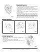
Product Manual
Pull out the hose until the latch pawl is engaged.
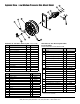
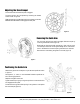
The hose bumper may be adjusted by loosening the slotted
screws shown in figure 6.
Slide the bumper to the desired position and tighten the screws
BEFORE PULLING HOSE to disengage the latch pawl.
Adjusting the Hose Bumper
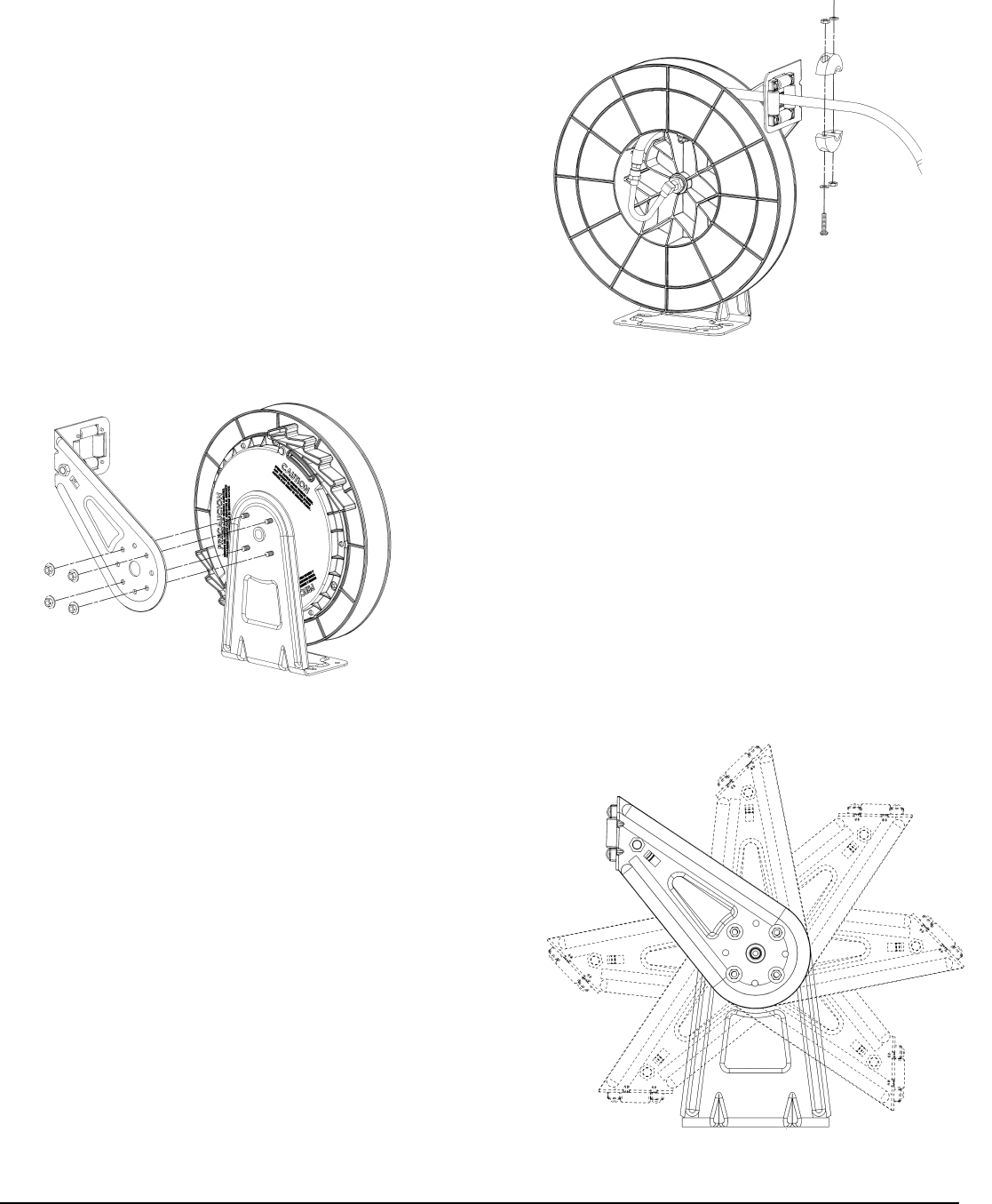
Removing the Guide Arm
Pull out hose until the latch pawl is engaged. Remove bumper by
removing the slotted screws (figure 6).
Disengage the latch pawl while maintaining a firm hold on spool.
Turn the spool hand over hand approximately two or three revolu-
tions in the direction of the drive spring until tension is removed.
Remove the 4 nuts holding the guide arm to base (figure 7).
figure 6
figure 7
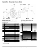
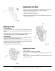
Remove the guide arm and adjust to any of the seven positions shown
in figure 8.
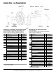
See figures 2, 3, and 4, for recommended Guide Arm positions for
each mounting application.
Replace and tighten the 4 nuts.
Tighten the drive spring by turning the spool two or three revolutions
and engage the latch pawl.
Pull the hose through the roller opening in the guide arm and replace
the hose bumper (figure 6)
Positioning the Guide Arm
figure 8
Reelcraft Industries, Inc. • 2842 E Business Hwy 30, Columbia City, IN 46725
(800) 444-3134 / (260) 248-8188 • Fax: (260) 248-2605 • www.reelcraft.com