Series RT Patent No. 7, 150, 425 Series RT Spring Driven Hose Reels Operating Instructions Thank you for purchasing a Reelcraft product. We wish you success in the critical function it will provide you in your business, home or garage. We invite your comments, ideas and suggestions. Someone is waiting to talk with you at 1-800-444-3134. Form No. 1121-802 Wind Things Up With Reelcraft TM Rev.
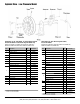
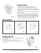
Exploded View - Low Pressure Model Low Pressure, all 1/4” hose models - 25, 35 and 50 foot long hose and 3/8” hose models - 25 and 35 foot long hose models only (RT402-OLP, RT425-OLP, RT403-OLP, RT435-OLP, RT405-OLP, RT450-OLP, RT602-OLP, RT625-OLP, RT603-OLP, RT635-OLP) Item Description Qty.
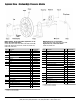
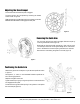
Exploded View - Medium/High Pressure Models Medium Pressure, all 3/8” hose models, High Pressure, all 1/4” models, 3/8” 25 foot hose models (RT602-OMP, RT625-OMP, RT603-OMP, RT635-OMP, RT605-OMP, RT650-OMP, RT402-OHP, RT425-OHP, RT403-OHP, RT435-OHP, RT602-OHP, RT625-OHP) Item 1 Description Qty Part Number Medium Pressure, all 1/2” hose models RT802-OMP, RT825-OMP, RT803-OMP, RT835-OMP High Pressure, 3/8”, 35 foot hose models RT603-OHP, RT635-OHP Item Description Qty.
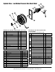
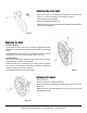
Exploded View - Low/Medium Pressure Side Mount Model Low Pressure 1/4” hose model - 50 foot long hose (RT450-OLPSM) Item Description Qty.
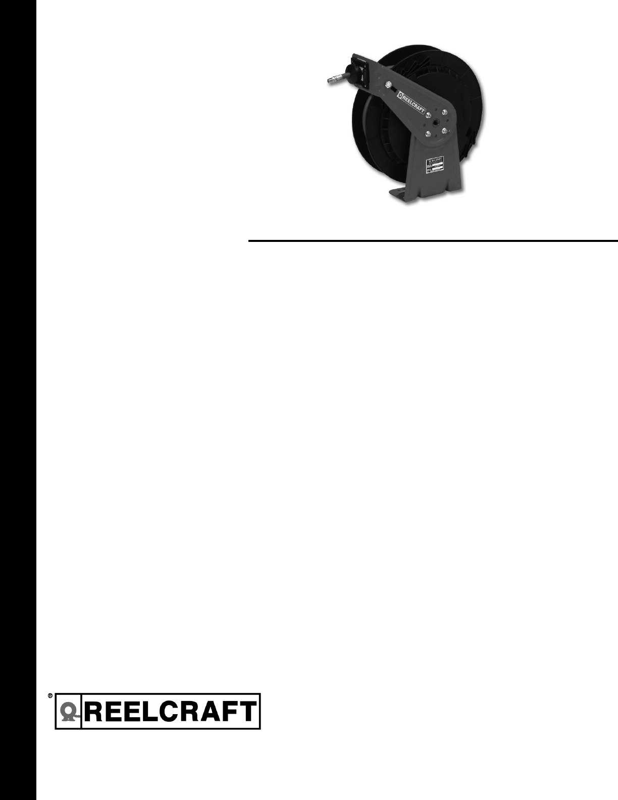
Mounting the Hose Reel Prior to mounting the hose reel, ensure that the supply line pressure does not exceed the maximum working pressure of the hose reel. Do not exceed the maximum installation height of 16’ unless the reel was specified differently when ordering. The maximum operating temperature is 150°F (66°C). Unpack and inspect the reel for damage. Turn the spool by hand to check for a smooth operation. figure 1 Position the reel on the floor, wall or ceiling.
Adjusting the Hose Bumper Pull out the hose until the latch pawl is engaged. The hose bumper may be adjusted by loosening the slotted screws shown in figure 6. Slide the bumper to the desired position and tighten the screws BEFORE PULLING HOSE to disengage the latch pawl. figure 6 Removing the Guide Arm Pull out hose until the latch pawl is engaged. Remove bumper by removing the slotted screws (figure 6). Disengage the latch pawl while maintaining a firm hold on spool.
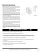
Replacing the Latch Pawl Remove the guide arm by following the procedure for “Removing the Guide Arm”. Remove the retaining nut as shown in figure 9. Replace the latch pawl assembly. Replace and tighten the retaining nut. Replace the guide arm and hose bumper by following the procedure for “Positioning the Guide Arm”. figure 9 Replacing the Hose To remove the hose Pull out the hose leaving 2 to 3 feet on the spool. Engage the latch pawl. Remove the U-bolt nuts on the inside of the spool (figure 10).
Replacing the Spool Assembly Attach the reel securely to prevent it from moving. Pull out the hose just until the latch pawl is engaged. Remove the hose bumper by removing the slotted screws (figure 6). Disengage the latch pawl while maintaining a firm hold on the spool. Turn the spool hand over hand approximately two or three revolutions until the spring tension is removed. Unscrew the swivel stem from the main shaft. Next, remove the swivel by unscrewing the swivel from the hose (figure 11).