
User Manual
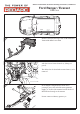

Open the trailer socket (7-pin shown as example);
remove any cable clamp and peel back boot (if t-
ted).
Feed RED of TWIN CORE (2) under boot, and
combine with existing RED (1) in terminal 6 posi-
tion and re-tighten.
1
6
5
3
2
7
4
2
1
1
6
5
3
2
7
4
2
1
3
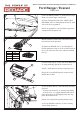
If any BLUE is tted to terminal 5 position, remove
and insulate, pulling back to main harness.
Feed BLUE (1) of TWIN CORE to terminal 5 and
tighten.
Ret any clamp (2) and boot, and wrap in insulating
tape to secure (3).
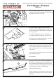
Secure BLACK fused wire (1) to existing wiring, con-
necting the eyelet to the Positive terminal (2).
Seal the wire at the grommet (step 3) with wraps of
electrical tape.
2
1
FIDoc# - TPWKIT-012-FI 4Page of 5 Issue# - 4 Date - 04/09/2019
TPWKIT-012
Electric Trailer Brake Controller Kit tting instructions, suitable for:
Ford Ranger / Everest
12
13
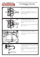
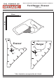
Test the installation using a test load (recommended
21W globe or equivalent) between terminal 5 and 3
on the trailer socket.
Perform a ‘Mode Change’ as per user manual - this
will only be successful if the wiring is connected
properly.
Ensure the unit is le in Proportional Mode for use.
1-
6-
5-
3-
2-
7-
4-
White Wire Pin#3
Blue Wire Pin#5
Filament Globe Test Light
15
14