
User Manual


Suitable for: Amarok Utility
FI13205
Issue: 4 Date: 14/08/2018
Kit Part No: TPWKIT-010
© 2018
14
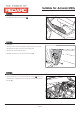
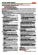
Step 19
Step 20
Step 21
4
7
2
3
5
6
1
2
1
• Remove the ‘BLUE’ wire (pin 5) (1) from the trailer wiring harness
socket head (2).
• Tape back and isolate.
• Insert new ‘BLUE’ wire with brass ferrule from the Electric Brake
Harness into the same position in the trailer socket.
Pin No.
Function
Cable Colour
1
2
3
4
5
6
7
Left-hand turn signal
Reversing signal
Earth return
Right-hand signal
Service brakes
Stop lamp signal
Rear lamps, clearance and
side marker lamps
Yellow
Black
White
Green
Blue
Red
Brown
Page 11 of
4
7
2
3
5
6
1
1
150mm
X
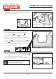
• Locate ‘RED’ wire (pin 6) (1) on the trailer wiring harness socket
head.
• Cut the wire 150mm from the base of the socket.
Note: If the wiring from the 7-pin socket is a 7-core cable, strip the
outer insulation back past 150mm from the socket so the red wire
can be accessed, once installation is complete, cover the wiring
with PVC tape to re-insulate.
Pin No.
Function
Cable Colour
1
2
3
4
5
6
7
Left-hand turn signal
Reversing signal
Earth return
Right-hand signal
Service brakes
Stop lamp signal
Rear lamps, clearance and
side marker lamps
Yellow
Black
White
Green
Blue
Red
Brown
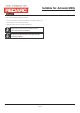
1 2
3 4
• Butt-splice and heat shrink the previously cut ‘RED’ wire on the
vehicle end, to the ‘RED/WHITE’ wire on the Electric Brake Harness.
Keep heatshrink away from joint until after soldering is
complete and cooled.
- Crimp both wires to the butt splice using indent type crimpers.
- Solder the wires to the butt splice. Ensure that a good
connection is made.
• Remove the cut ‘RED’ wire (pin 6) from the trailer socket.
• Insert new ‘RED’ wire with brass ferrule from the Electric Brake
Harness into the same position in the trailer socket.
- Wait for the butt splice to cool, slip heatshrink over the joint and
heat.