
User Manual


FI11979
Issue: 4 Date: 14/08/2018
© 2018
Kit Part No: TPWKIT-007
Suitable for: Kluger / Prado
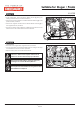
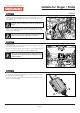
Step 22
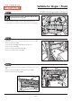
Step 23
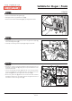
Step 24
Page 11 of
• Remove the ‘BLUE’ wire (1) from the trailer wiring harness socket
head (2).
• Tape back and isolate.
• Insert new ‘BLUE’ wire with brass ferrule from the Electric Brake
Harness into the same position in the trailer socket.
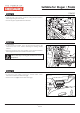
Pin No.
Function
Cable Colour
1
2
3
4
5
6
7
Left-hand turn signal
Reversing signal
Earth return
Right-hand signal
Service brakes
Stop lamp signal
Rear lamps, clearance and
side marker lamps
Yellow
Black
White
Green
Blue
Red
Brown
4
7
2
3
5
6
1
2
1
• Locate ‘RED’ wire (1) on the trailer wiring harness socket head.
• Cut the wire 150mm from the base of the socket.
• Remove the cut ‘RED’ wire (1) from the trailer socket.
4
7
2
3
5
6
1
Pin No.
Function
Cable Colour
1
2
3
4
5
6
7
Left-hand turn signal
Reversing signal
Earth return
Right-hand signal
Service brakes
Stop lamp signal
Rear lamps, clearance and
side marker lamps
Yellow
Black
White
Green
Blue
Red
Brown
1
150mm
X
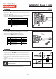
• Butt-splice and heat shrink the previously cut ‘RED’ wire on the
vehicle end, to the ‘RED/WHITE’ wire on the Electric Brake Harness.
• Slide the supplied Heatshrink over the wires before c
•
•
rimping both
wires to the supplied Butt Splice using indent type crimpers.
Solder the wires to the Butt Splice. Ensure that a good connection
is made.
Wait for the Butt Splice to cool, slip heatshrink over the joint and
heat.
Keep heatshrink away from joint until after soldering is
complete and cooled.
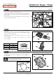
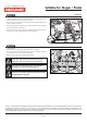
• Insert new ‘RED’ wire with brass ferrule from the Electric Brake
Harness into the same position in the trailer socket.
1 2
3 4
1
1
2
Red
Red/White
Red/White
KLUGER
21