
User Manual


Suitable for: Landcruiser LC200
FI11848
Issue: 4 Date: 14/08/2018
Kit Part No: TPWKIT-005
© 2018
4
3
1
2
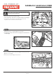
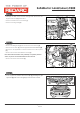
• Secure the Brake Controller ECU (1) to the ECU Bracket (2) using
the supplied M4 Flat Washers (3) and M4 Nyloc Nuts (4).
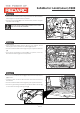
• Locate the RHS firewall grommet. Cut an access point on the
outer side of the RHS grommet. Lubricate the grommet access
point (1) with a suitable lubrication if required.
• Secure the section of the Electric Brake Harness (2) with four
terminals to a guide wire using tape. Keep the thickness of the
taped section small. Feed the guide wire into the previously cut
RHS access point of the firewall grommet.
• Ensure the guide wire breaks the internal seal and is fed into the
RHS of the cabin.
• Continue feeding the soft tube section of the harness into the
cabin until the junction meets the grommet.
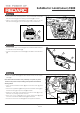
• Secure the Electric Brake Harness to the vehicle harness and seal
the grommet with silastic and a supplied Cable Tie (3).
• To reduce risk of water ingress, create a small loop (4) on the
harness below the grommet entry using either tape or cable tie.
• Discard the guide wire after routing.
(1)
1
Page 08 of
Step 13
Step 14
Step 15
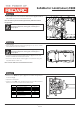
• Inside the vehicle, using the table below, house the terminals (1)
from the Electric Brake Harness into the supplied 4-Way
Connector (2), ensuring the terminals lock into the housing.
• Snap off the secondary lock (3) from behind the 4-Way
Connector (2).
• Fit the secondary lock (3) to the underside of the 4-Way
Connector (2).
Wire Colour
Terminal
1
2
3
4
Red
Blue
White
Black
Rear View of Connector
(Wire Entry Side)
4 3 2 1
2
3
3
2
4-way ECU
connector
Cat 5
Cable
Connector
1
3
4
2
13