
User Manual


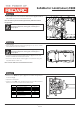

Suitable for: Landcruiser LC200
FI11848
Issue: 4 Date: 14/08/2018
Kit Part No: TPWKIT-005
© 2018
Page 11 of
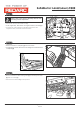
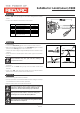
Step 22
Step 23
• Locate ‘RED’ wire (pin 6) (1) on the trailer wiring harness socket
head.
• Cut the wire 150mm from the base of the socket.
4
7
2
3
5
6
1
Pin No.
Function
Cable Colour
1
2
3
4
5
6
7
Left-hand turn signal
Reversing signal
Earth return
Right-hand signal
Service brakes
Stop lamp signal
Rear lamps, clearance and
side marker lamps
Yellow
Black
White
Green
Blue
Red
Brown
1
150mm
X
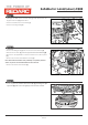
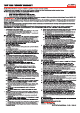
• Locate the ‘RED/WHITE’ (1) wire from the Electric Brake Harness.
• Slide the supplied Heatshrink over the ‘RED/WHITE’ (1) wire and the
previously cut ‘RED’ (2) wire on the vehicle end.
• Crimp both wires using the supplied Butt Splice with an indent type
crimper.
• Solder the wires to the Butt Splice. Ensure that a good connection
is made.
1 2
3 4
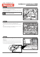
Keep heatshrink away from joint until after soldering is
complete and cooled.
• Wait for the Butt Splice to cool, slip the heatshrink over the joint
and heat.
• Remove the cut ‘RED’ wire (pin 6) from the trailer socket and
discard.
• Insert new ‘RED’ wire with brass ferrule from the Electric Brake
Harness into the same position in the trailer socket.
• Re-connect negative battery terminal.
• Test the operation of the Electric Brake Harness using a test lamp
or a multimeter to ensure correct operation.
• Dispose of any parts not used from the fitment.
Please place the Owners Manual in the glov box after
installation completed.
e
the is
Important
Secure all harnesses to the vehicle using the supplied
cable ties. Refit all removed parts and secure all
fasteners to Service Manual torque specifications.
Important
Reprogram all radio stations and clock settings by
referring to the vehicle's Workshop Manual.
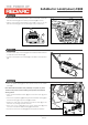
Step 24
1
1
2
Red
Red/White
Red/White
13