
User Manual

Suitable for: Mitsubishi Triton
FI11705
Issue: 4 Date: 14/08/2018
Kit Part No: TPWKIT-003
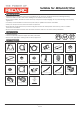
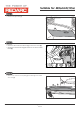
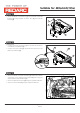
Step 17
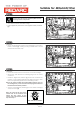
Step 16
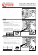
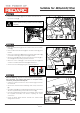
Step 18
• Insert the Switch Insert (1) into the vacant cavity on the switch
panel (2).
• Insert the Electric Brake Switch (3) into the Switch Insert (1) from
behind.
• Fasten the supplied Nut (4) locking the Electric Brake Switch (3)
to the Switch Insert (1). Torque the nut (4) to 0.8Nm.
• Rotate the shaft (5) fully anti-clockwise and fit the knob (6) to
the shaft (5) with “0" pointing upwards as shown.
• Route the Cat 5 Cable (7) to the switch panel area (2) and
connect to the Electric Brake Switch (3) from behind.
• Secure the Cat 5 Cable (7) using the supplied Cable Ties.
2
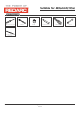
Note: The following step are for vehicle’s with an unoccupied 3-
way connector. For vehicle’s that have an occupied 3-way
connector, please proceed to Step 20.
• Under the vehicle, locate the 3-way connector (1) at the rear
LH chassis rail.
• Disconnect and discard the blanking male 3-way connector
(2).
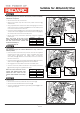
• Fit the Blue Wire (3) from the Brake Signal Harness into the cavity
‘2' of the supplied mating 3-Way Male Connector (4).
• Insert the supplied Plug Seals into the remaining cavities and fit
the supplied Secondary Lock before re-joining the 3-way
connectors.
• Route the Brake Signal Harness towards the vehicle trailer
wiring harness socket.
1
2
3
4
Page 10 of
1
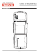
• Route the Cat 5 Cable (1) from the Brake Controller ECU to
the switch cavity (2).
2
1
1
7
3
6
4
5
1
Important
When routing the Cat 5 Cable (1), ensure it does not
interfere with the steering column or the knee airbag
in any way.
1
3
2
Front view of connector
5
6
12
© 2018