
User Manual

FORD RANGER / EVERESTSuitable for:
Kit Part No: TPWKIT-001
FI11409
Issue: 4 Date: 13/08/2018
17
© 2018
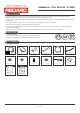
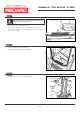
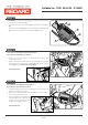
Step 10
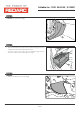
Step 11
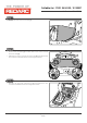
Step 12
• Secure the Brake Controller ECU (1) onto the Brake Controller
Bracket (2) using the supplied M4 Flat Washers (3) and M4 Nyloc
Nuts (4).
• Ensure the ECU orientation is correct, as shown.
• Attach the supplied Push Clip Cable Tie (5) to the Brake Controller
Bracket (2) as shown.
Page 08 of
• Cut out and adhere the appropriate supplied Switch Template
(1) (Page 17) to the gear shift surrounding trim (2), ensuring to
align them to the vehicle trim edges as indicated.
• Using a Ø2mm drill bit, drill out the pilot hole in the locations
specified on the template (1).
• Drill out the top hole to Ø3.5mm and the bottom hole to Ø10mm.
• Remove any plastic ribs interfering with the hole from behind.
5
3
2
1
1
•
•
•
•
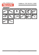
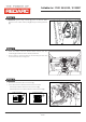
Plug the Cat 5 Cable (1) supplied in the wiring kit, into the remote
head (2) and fit the remote head to the gear shift surrounding trim
(3).
Secure the remote head to the surround trim (3) as shown. Torque
the nut (4)to 0.8 Nm using a 12mm socket.
Rotate the shaft (5) fully anti-clockwise and fit the knob (6) to the
shaft (5) with “0" pointing upwards as shown below.
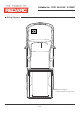
Route the Cat 5 Cable (1) towards the glove box area.
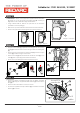
Everest
Ranger - Hi Spec
Ranger - Low Spec
1
2
1
2
4
3
5
Cat 5
cable
4-way ECU
connector
5
4
6
5
6