
User Manual

FORD RANGER / EVERESTSuitable for:
Kit Part No: TPWKIT-001
FI11409
Issue: 4 Date: 13/08/2018
17
© 2018
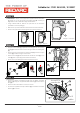
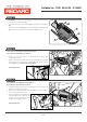
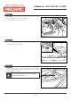
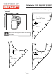
Step 30
Page 15 of
• Route the positive ring terminal (1) from the Electric Brake Harness
(2) along the chassis rail towards the engine bay.
• Secure with the supplied 900mm Cable Ties.
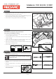
• In the engine bay, fasten the positive Electric Brake Harness ring
terminal (1) to the vehicle positive post (3) located behind the
fuse box.
• Secure the Fuse Holder (4) to the vehicle bracket as shown using
supplied Cable Ties (5).
• Secure the Electric Brake Harness (2) in the engine bay using the
supplied 200mm Cable Ties.
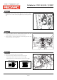
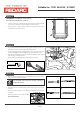
Step 31
• Reconnect the engine bay negative battery terminal.
• Test the operation of the Electric Brake Harness using a test lamp
or a multimeter to ensure correct operation.
• Dispose of any parts not used from the fitment.
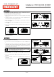
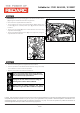
Important
Secure all harnesses to the vehicle using cable ties.
Refit all removed parts and secure all fasteners to the
Service Manual torque specifications.
Important
Reprogram all radio stations and clock settings by
referring to the vehicle's Owner's Manual.
Please place the
in the glov box after installation completed.
Fitting Instructions and Owner's
Manual e is
E. & O.E. This document is copyright and must not be used except as permitted below or under the Copyright Act 1968. You may reproduce
and publish this document in whole or in part for your or your organisation's own personal or internal compliance, educational or non-
commercial purposes. You must not alter or amend this document in any way. You must not reproduce or publish this document for
commercial gain without the prior written consent of the copyright owner.
2
1
3
1
3
2
2
1
3
3
1
3
4
4
1 1
1
1
1
1
1
1
1
1
1
1
P
P
A
A
A
A
Nissan pointers
P
P
Common Fasteners
Pointers
5