
User Manual

FORD RANGER / EVERESTSuitable for:
Kit Part No: TPWKIT-001
FI11409
Issue: 4 Date: 13/08/2018
17
© 2018
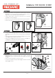
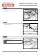
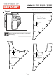
Step 24
Step 25
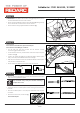
Step 26
3
3
•
• Route the Electric Brake Harness circuit breaker (2) along the top
of the chassis rail towards the front of the vehicle.
•
Route the Electric Brake Harness blue wire (1) along the top of the
chassis rail towards the rear of the vehicle.
Secure Harness using supplied 900mm Cable Ties (3).
3
1
2
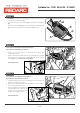
If the vehicle is a Ford Everest, proceed to Step 27.
If the vehicle is a Ford Ranger, continue:
1
•
•
•
•
•
On the LHS rear tub area, locate the OE Harness 16-way
connector (1) and disconnect.
On the male connector, peel the back of the PVC tape to expose
the blue wire (2).
Locate the White Tape (3) on the Electric Brake Harness (blue
wire), cut at this point and discard the extra length.
Strip 5mm of insulation from both the Electric Brake Harness (blue
wire) and the vehicle blue wire.
Route the Electric Brake Harness (blue wire) to this area.
2
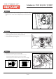
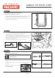
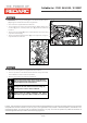
• Slip the supplied Heatshrink over the wire and insert both blue
wires into the supplied Butt Splice.
1
• C
•
•
•
rimp both wires to the Butt Splice using indent type crimpers.
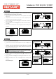
Solder the wires to the Butt Splice. Ensure that a good connection
is made.
Wait for the Butt Splice to cool, slip the Heatshrink over the joint
and heat.
Reconnect the 16-way connector (1).
Keep heatshrink away from joint until after soldering is
complete and cooled.
Proceed to Step 30.
Page 13 of
3
1 2
3 4