
User Manual

FORD RANGER / EVERESTSuitable for:
Kit Part No: TPWKIT-001
FI11409
Issue: 4 Date: 13/08/2018
17
© 2018
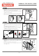
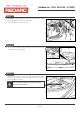
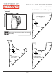
Step 19
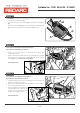
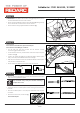
Step 20
Page 11 of
4-Way Connector
2-Way Connector
3
1
1
3
For all models excluding PX2 Ranger XL Plus, continue with step 19.
For PX2 Ranger XL Plus models, go to step 20.
• Select the appropriate patch from the two supplied in the wiring
harness kit.
• If required, release the secondary locks on the supplied patch
connectors before housing the terminals.
• House the RED female terminal (1) into the female connector
empty cavity (2).
• House the RED male terminal (3) into the male connector empty
cavity (4).
• Ensure the secondary locks are re-engaged after inserting the
terminals.
Front view female connector Front view female connector
2
1
4 1
4-Way Connector2-Way Connector
4-Way Connector
4-Way Connector
2
1
3
4
4
3
2
6
5
For PX2 Ranger XL Plus models only.
• On the 4-way Connector Patch (1) locate the grey wire (2) on Pin
1.
• Carefully de-house the GREY wire male (3) and female (4)
terminals, using a small flat blade jeweller’s screwdriver to lower
the terminal locking tab before gently pulling the terminal out
from the rear of the connector.
• House the GREY wire male (3) and female (4) terminals into the
pin 4 location.
• House the RED female (5) and male (6) terminals into pin 1
location.
• Ensure secondary locks are re-engaged after inserting the
terminals.
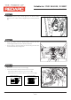
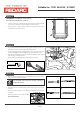
Front view female connector
4 1
4-Way Connector
Grey White Black Red
Proceed to Step 21.
Proceed to Step 21.
4
2
4
2
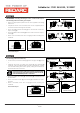
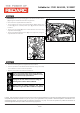
Male connector Female connector
Before dehousing the male terminal, pull the terminal locking
plate forward by levering out through the top of the connector
with a small flat blade jeweller’s screwdriver.