
Product Manual


KEY FEATURES
• Charges Standard, Calcium, AGM or Gel Lead Acid batteries (User Selectable via
push button switch)
• Recharges batteries to 100% capacity
• Reverse polarity connection protection, charging commences after the battery
has been connected correctly
• Output short circuit protection
• Battery overcharge protection
• Faulty battery cell detection and safe charge termination
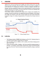
• 4-Stage Charging Pattern with timeout protection
• Initial self test on power up
• Over temperature shut down
• Light and ultra compact
• Latest switch mode design
• Safety and EMC compliance
• Designed and manufactured in Australia for Australian conditions
1 INSTALLATION
The charger must be placed in a well ventilated position to allow air fl ow to cool the
charger for greater charging effi ciency. The charger should be placed in a safe, secure
position where the charger is not likely to fall down.
NOTE: Never place the charger on top of the battery.
Leave the vent caps closed as modern automotive batteries have a gas recombination
design built into the cap to allow the retention of the gassed electrolyte and its return to
the battery cell. All vent caps also have a venting system to allow excessive gasses to
escape. Coin screwed cap designs also have a “manifold” venting system, which works
in the same way as a screwed vent cap.
1.1 Connections
If the battery is in a vehicle disconnect the negative battery terminal from the battery.
Connect the RED clip to positive and the BLACK clip to negative. Ensure the connections
are tight and sound. Then connect the 240VAC three pin plug to the power point and
switch on the power. Then switch on the Smart Battery Charger power switch (located
on the rear panel). Once turned ON, the charger will pause momentarily, then light up all
the indicators in a sequence so you can see that they are all functional. The cooling fan
will also be run up and tested during this sequence.
3