
Specifications


SECTION 7 CESSNA
AIRPLANE AND SYSTEM DESCRIPTION MODEL 172R NAV III
GFC 700 AFCS
U.S.
AVIONICS SUPPORT EQUIPMENT (Continued)
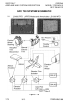
ANTENNAS
Two dual-mode VHF COM/GPS antennas are mounted on the top of
the cabin. The COM 1/GPS 1 antenna is mounted on the right side and
the COM 2/GPS 2 antenna is mounted on the left side. They are
connected to the two VHF communication transceivers and the two
GPS receivers in the integrated avionics units.
The GDL antenna is also mounted on the top of the cabin. It provides a
signal to the GDL-69A XM Data Link receiver.
A blade-type navigation antenna is mounted on either side of the
vertical stabilizer. This antenna provides VOR and glideslope signals to
the VHF navigation receivers contained in the integrated avionics units.
The marker beacon antenna is mounted on the bottom of the tailcone.
It provides the signal to the marker beacon receiver located in the audio
panel.
The transponder antenna is mounted on the bottom of the cabin and is
connected to the Mode S transponder by a coaxial transmission cable.
The Bendix/King Distance Measuring Equipment (DME) antenna (if
installed) is mounted on the bottom of the tailcone and is connected to
the Bendix/King DME receiver by a coaxial cable.
(Continued Next Page)
172RPHBUS-00
7-74