
Specifications

SECTION 7 CESSNA
AIRPLANE AND SYSTEM DESCRIPTION MODEL 172R NAV III
GFC 700 AFCS
U.S.
CABIN HEATING, VENTILATING AND DEFROSTING
SYSTEM
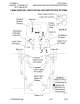
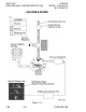
The temperature and volume of airflow into the cabin can be regulated
by manipulation of the push-pull CABIN HT and CABIN AIR control
knobs, Refer to Figure 7-8. Both control knobs are the double button
locking-type and permit intermediate control settings.
For cabin ventilation, pull the CABIN AIR control knob full out. To raise
the air temperature, pull the CABIN HT control knob out approximately
1/4 to 1/2 inch for a small amount of cabin heat. Additional heat is
available by pulling the CABIN HT control knob out farther; maximum
heat is available with the CABIN HT control knob pulled full out and the
CABIN AIR control knob pushed full in. When no heat is desired in the
cabin, the CABIN HT control knob is pushed full in.
Front cabin heat and ventilating air is supplied by outlet holes spaced
across a cabin manifold just forward of the pilot's and front passenger's
feet. Rear cabin heat and air is supplied by two ducts from the manifold,
one extending down each side of the cabin to an outlet just aft of the
rudder pedals at floor level. Windshield defrost air is also supplied by
two ducts leading from the cabin manifold to defroster outlets near the
lower edge of the windshield. Two knobs control sliding valves in either
defroster outlet to permit regulation of defroster airflow.
Separate adjustable ventilators supply additional air; one near each
upper corner of the windshield supplies air for the pilot and front
passenger, and two ventilators are available for the rear cabin area to
supply air to the rear seat passengers. There are additional ventilators
located in various positions in the cockpit.
172RPHBUS-00
7-62