
Specifications

SECTION 7 CESSNA
AIRPLANE AND SYSTEM DESCRIPTION MODEL 172R NAV III
GFC 700 AFCS
U.S.
ENGINE (Continued)
ENGINE INSTRUMENTS
The G1000 Engine Indication System (EIS) provides graphical
indicators and numeric values for engine, fuel, and electrical system
parameters to the pilot. The EIS is shown in a vertical strip on the left
side of the PFD during engine starts and on the MFD during normal
operation. If either the MFD or PFD fails during flight, the EIS is shown
on the remaining display.
The EIS consists of three pages that are selected using the ENGINE
softkey. The ENGINE page provides indicators for Tachometer (RPM),
Fuel Flow (FFLOW GPH), Oil Pressure (OIL PRES), Oil Temperature
(OIL TEMP), Exhaust Gas Temperature (EGT), Vacuum (VAC), Fuel
Quantity (FUEL QTY GAL), Engine Hours (ENG HRS), Electrical Bus
Voltages (VOLTS), and Battery Currents (AMPS). When the ENGINE
softkey is pressed, the LEAN and SYSTEM softkeys appear adjacent to
the ENGINE softkey. The LEAN page provides simultaneous indicators
for Exhaust Gas Temperature (EGT °F) and Cylinder Head
Temperature (CHT °F) on all cylinders to be used for adjusting, or
leaning, the fuel/air mixture along with a digital value for FFLOW GPH
and a indicator for FUEL QTY GAL. The SYSTEM page provides
numerical values for parameters on the ENGINE page that are shown
as indicators only. The SYSTEM page also provides a digital value for
Fuel Used (GAL USED) and Fuel Remaining (GAL REM).
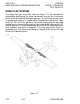
The engine and airframe unit, located forward of the instrument panel,
receives signals from the engine/system sensors for the parameters
that are being monitored. The engine and airframe unit provides data to
the EIS, which displays the data for the ENGINE page described on the
following pages.
(Continued Next Page)
172RPHBUS-00
7-30