
Specifications

CESSNA SECTION 7
MODEL 172R NAV III AIRPLANE AND SYSTEM DESCRIPTION
GFC 700 AFCS
U.S.
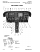
INSTRUMENT PANEL (Continued)
RIGHT PANEL LAYOUT
The Emergency Locator Transmitter (ELT) remote switch (ON/ARM/
TEST RESET) is positioned at the upper inboard corner of the right
panel adjacent to the MFD. Refer to Section 9, Supplements 1 or 2 for
appropriate ELT operating information.
The Hour (Hobbs) meter is found to the right of the ELT switch and
records engine operating time, when oil pressure is greater than 20
PSI, for maintenance purposes. Refer to the ENGINE INSTRUMENTS
description in this section for further information.
CENTER PEDESTAL LAYOUT
The center pedestal, located below the center panel, contains the
elevator trim control wheel, trim position indicator, 12V power outlet,
aux audio input jack, fuel shutoff valve, and the hand-held microphone.
The fuel selector valve handle is located at the base of the pedestal.
172RPHBUS-00
7-13