
User Manual
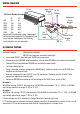

WIRING DIAGRAM
IN-VEHICLE TESTING
Equipment needed: Multimeter or voltmeter.
5W/24V test lamp with connection leads/clips.
• Leave input (VIOLET) wire and earth (GREEN) wire connected.
• Disconnect output (BROWN) wire from battery. (Do not allow BROWN wire to contact chassis/earth).
• Connect 5W test lamp between BROWN wire and vehicle chassis/earth.
• The lamp should light up.
• Using a voltmeter, measure voltage on the BROWN wire. (Voltmeter positive wire to BROWN wire,
negative wire to chassis/earth)
• Measure voltage on the input (VIOLET) wire 24V connection. (Voltmeter positive to VIOLET wire
connection, negative to chassis/earth)
• Voltage on BROWN wire should be half the voltage on the VIOLET wire. (within 0.25V)
Example 1.
With Motor running, if VIOLET wire measures 28V, BROWN wire should be 14V (+/- 0.25V), i.e. BROWN
wire voltage should be in range 13.75V to 14.25V.
Example 2.
With Motor not running, if VIOLET wire measures 24V, BROWN wire should be 12V (+/- .25V), i.e. BROWN
wire voltage should be in range 11.75V to 12.25V.
If these voltages are OK, it indicates the Charge Equaliser is operating correctly.
If 12V battery does not maintain the correct voltage, check that all connections are sound. If this is all OK,
measure the 12V current draws and check that the Charge Equaliser is suitably rated.
Input Circuit
Breaker*
24V
Battery
Bank
Chassis
Earth
Not
supplied
To 24V
System
Output Circuit
Breaker*
Not
supplied
Equipment
Circuit
Breaker*
Not
supplied
CE Unit
*CE Circuit Breaker Ratings
I/P O/P
CE3 5A 5A
CE10 15A 15A
CE20 15A 20A
CE30 20A 35A
CE40 30A 50A
CE60 50A 80A
Equipment Circuit Breaker rating is dependant
on the total load rating of all the equipment used.
Fuses may be used however self resetting
circuit breakers are recommended.
Purple
Green
Brown