
User Manual
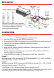

WIRING
For maximum effi ciency the Charge Equaliser must be fi tted as close as practical to the lower battery.
Fuses or circuit breakers (not provided) MUST be fi tted to the input and output wires as outlined in the
diagram and as per the precautions below. The fuses are essential to ensure the safety of the vehicle’s
wiring in the event of a short circuit. Connection of the violet wire to 24 volt can be made in two ways;
• If a permanent connection is required, the VIOLET (RED on CE60) wire can be connected to the 24V
battery terminal. In this case there is a small standby current and as with any permanent electrical
load the fuse should be removed if the vehicle is to be left un-used for extended periods.
• If the Charge Equaliser is to be turned off when the vehicle is not in use or if there is an isolator
switch on the positive 24V side, the 24V feed to the violet wire must be via a relay operated by the
ignition switch. Failure to use a relay will allow the 12V battery to discharge back via the Charge
Equaliser to any other equipment connected to the 24V system.
• An incorrect 24V output reading will be recorded if checking the output without a load attached.
Refer to in-vehicle testing.
• It is recommended that the case be insulated if negative isolation of the 24V battery bank is used.
PRECAUTIONS
1. During installation of the Charge Equaliser ensure that the 12V terminal is connected last and
disconnected fi rst. A small spark is normal whilst connecting.
2. A sound earth connection is essential (See wiring diagram for fi tting the Charge Equaliser).
3. If jump starting the vehicle, the CE must be isolated by removal of the fuses to prevent damage.
4. Avoid direct steam/pressure cleaning of the unit as the chemicals used in the fl uids can be corrosive.
5. A fuse must be fi tted between the 12V battery terminal and any 12V equipment.
6. If fi tted to a vehicle with an isolator switch on the negative earth side the 30, 40 and 60 amp
Charge Equalisers’ case must then be insulated from chassis and the earth wire of the CE returned
to the negative pole of the 12V battery.
7. Do not use in conjunction with a Pulsing Desulphator.
Note: Redarc suggests an ignition controlled relay or SBI24 be fi tted to control the 24Volt input to the charge
equaliser should the vehicle be left unattended for excessive lengths of time. Doing so this will switch off the charge
equaliser protecting the 24Volt output battery from excessive discharge whilst the vehicle is not in operation.
Note: To prevent serious damage to the CE, care must be taken to avoid the following:
Swapping 24V Input and ground connections
Swapping 24V Input and 12V Output connections
Swapping 12V Output and ground connections
Damage will also occur if:
Any large load is connected to the 24V system while an isolator switch is open. This applies to positive or negative
isolator switches in the 24V battery bank.
(To protect against this fi t an ignition relay or SBI24 solenoid)
The CE is charging an auxiliary 12V battery and any battery terminal in the 24V battery bank comes loose while 24V
load is applied.