PRO I/O MODULE O P E R AT I O N G U I D E FOR RED DSMC CAMERAS RED.
P R O I / O M O D U L E O P E R AT I O N G U I D E TABLE OF CONTENTS TABLE OF CONTENTS FEATURES SAFETY MOUNTING CONNECTIONS Audo Inputs Audio Output Auxiliary Power Output Digital Audio Input General Purpose Input/Output Genlock Program Output Preview Output RS232 Port Timecode EVF/LCD SPECIFICATIONS Weight Current Draw Temperature Ratings DIMENSIONED DRAWINGS COMPLIANCE STATEMENTS DISCLAIMER COPYRIGHT NOTICE TRADEMARK DISCLAIMER 2 2 3 4 4 4 4 5 5 5 6 6 6 6 7 7 8 8 8 8 8 8 9 11 11 11 955-0010, Rev-B / CO
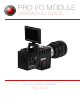
P R O I / O M O D U L E O P E R AT I O N G U I D E FEATURES For advanced configurations, the PRO I/O MODULE attaches to the rear of your DSMC brain to provide a central hub for essential I/O connections. Professional I/O support for audio and video is critical for large productions and the PRO I/O MODULE bundles them conveniently into one compact DSMC module.
P R O I / O M O D U L E O P E R AT I O N G U I D E SAFETY Important Safety Instructions Read Before Using Your Pro I/O MODULE • Heed all cautions and warnings in these instructions • Follow these instructions when using the PRO I/O MODULE • Keep these instructions with the PRO I/O MODULE at all times WARNING: Do not modify, dismantle or open this accessory as doing so may expose you to electric shock and serious injury.
P R O I / O M O D U L E O P E R AT I O N G U I D E AUDIO OUTPUT (OUT) • A 5-pin XLR connector supports two chan nels of balanced analog audio output PIN DESCRIPTION 1 (+) Line output, left channel 2 Camera Ground 3 (-) Line output, left channel 4 (+) Line output, right channel 5 (-) Line output, right channel 5-PIN XLR Facing PRO I/O MODULE AUXILIARY POWER OUTPUT (PWR) • Supplies unregulated (+) 11.5 to 17V battery passthrough power between pins 1 and 4 • Maximum sustained current draw: 1.
P R O I / O M O D U L E O P E R AT I O N G U I D E GENERAL PURPOSE INPUT/OUTPUT (GPIO) • Auxiliary power output connector with GPIO trigger/ tally function • Auxiliary output supplies unregulated 9-17V battery pass-through power between pins 1 and 4 • Maximum sustained current draw: 1.
P R O I / O M O D U L E O P E R AT I O N G U I D E RS232 PORT (AUX) • 10 pin interface fixed programmable function GPIO pins • Regulated 12V power at nominal 750 mA • RS232 remote camera control PIN DESCRIPTION 1 Camera ground 2 Primary RS232 TX 3 (+) 12V 4 GPO B - Programmable tally output Default: “record complete” When active, present 3.3 V @0.
P R O I / O M O D U L E O P E R AT I O N G U I D E EVF/LCD • Custom digital video and power interconnection between the camera and a RED EVF or RED LCD Monitor • The pin-out of this interface is not published • Contact RED technical support for available RED EVF cable lengths EVF/LCD Connector SPECIFICATIONS WEIGHT 2.4 lbs CURRENT DRAW 24W when used with RED 5” LCD TOUCHSCREEN AUXILIARY POWER OUTPUT 1.5 Amp continuous load at 11.
P R O I / O M O D U L E O P E R AT I O N G U I D E COMPLIANCE INDUSTRIAL CANADA EMISSION COMPLIANCE STATEMENTS This Class B digital apparatus complies with Canadian ICES-003. Cet appareil numérique de la classe A est conforme à la norme NMB-003 du Canada. FEDERAL COMMUNICATIONS COMMISSION (FCC) STATEMENT This equipment has been tested and found to comply with the limits for a class B digital device, pursuant to part 15 of the FCC Rules.
P R O I / O M O D U L E O P E R AT I O N G U I D E AUSTRALIA AND NEW ZEALAND STATEMENT This device has been tested and found to comply with the limits for a Class B digital device, pursuant to EN 55022:2006 JAPAN STATEMENTS This is a Class B product based on the standard of the Voluntary Control Council for Interference (VCCI) for information technology equipment. If this equipment is used near a radio or television receiver in a domestic environment, it may cause radio interference.
P R O I / O M O D U L E O P E R AT I O N G U I D E DISCLAIMER RED ® has made every effort to provide clear and accurate information in this Operation Guide, which is provided solely for the user’s information. While thought to be accurate, the information in this document is provided strictly “as is” and RED will not be held responsible for issues arising from typographical errors or user’s interpretation of the language used herein that is different from that intended by RED.