
User guide


Build 31 v31.6.16
NOVEMBER 28, 2011 © 2007-2011 RED.COM INC.
129
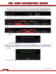
APPENDIX D: INPUT / OUTPUT CONNECTORS
RIGHT SIDE OF CAMERA
A
Headphone
H
USB-2 (computer)
B
Program HD-SDI (A)
I
Audio Monitor
C
Program HD-SDI (B)
J
Timecode
D
Preview HD-SDI
K
Audio Ch 1 – 4 (1-2 Upper Left
- Right, 3-4 Lower Left - Right)
E
Video Genlock
L
RED EVF
E
HDMI Out
M
RED LCD
G
USB-2 (peripheral)
N
Aux / RS232
TIMECODE INPUT / OUTPUT
This connector supports SMPTE Timecode input and output. Pins 2 and 3 may be used together to re-
ceive a balance SMPTE 12M serial time code input, or pin 2 may be used by itself (leave pin 3 open) to
receive a single-ended SMPTE 12M serial time code input. Pin 5 is time code output.
View into camera Timecode connector
Mating Connector: LEMO FGG.0B.305.CLAD42Z
A
N
L
M
K
J
I
H
G
F
E D
C B