
Operation Manual
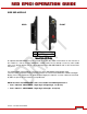
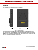
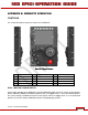
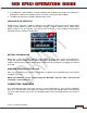
Table Of Contents
- RED EPIC® OPERATION GUIDE
- TABLE OF CONTENTS
- DISCLAIMER
- COMPLIANCE
- BEFORE YOU START
- THEORY OF OPERATION
- CAMERA OPERATIONAL CONTROLS
- BASIC OPERATION
- FIRST TIME USE – SETTING UP YOUR RED EPIC
- MENU CONTROLS
- MAIN MENU
- SECONDARY MENUS
- APPENDIX A: UPGRADING CAMERA FIRMWARE
- APPENDIX B: MANAGING DIGITAL MEDIA
- APPENDIX C: CHARGING BATTERIES
- APPENDIX D: INPUT / OUTPUT CONNECTORS
- APPENDIX E: REDMOTE OPERATION
- APPENDIX F: 3D SETUP / OPERATION
- APPENDIX G: EXPOSURE – USING FALSE COLOR AND ISO
- APPENDIX H: POST PRODUCTION
- APPENDIX I: TROUBLESHOOTING
- APPENDIX J: MAINTENANCE
- APPENDIX K: TECHNICAL DATA
- APPENDIX L: MENU MAPS
Version 1.4.0 SVN 29352 BETA
©2011 RED.COM INC. APRIL 19, 2011
132 132
REDMOTE
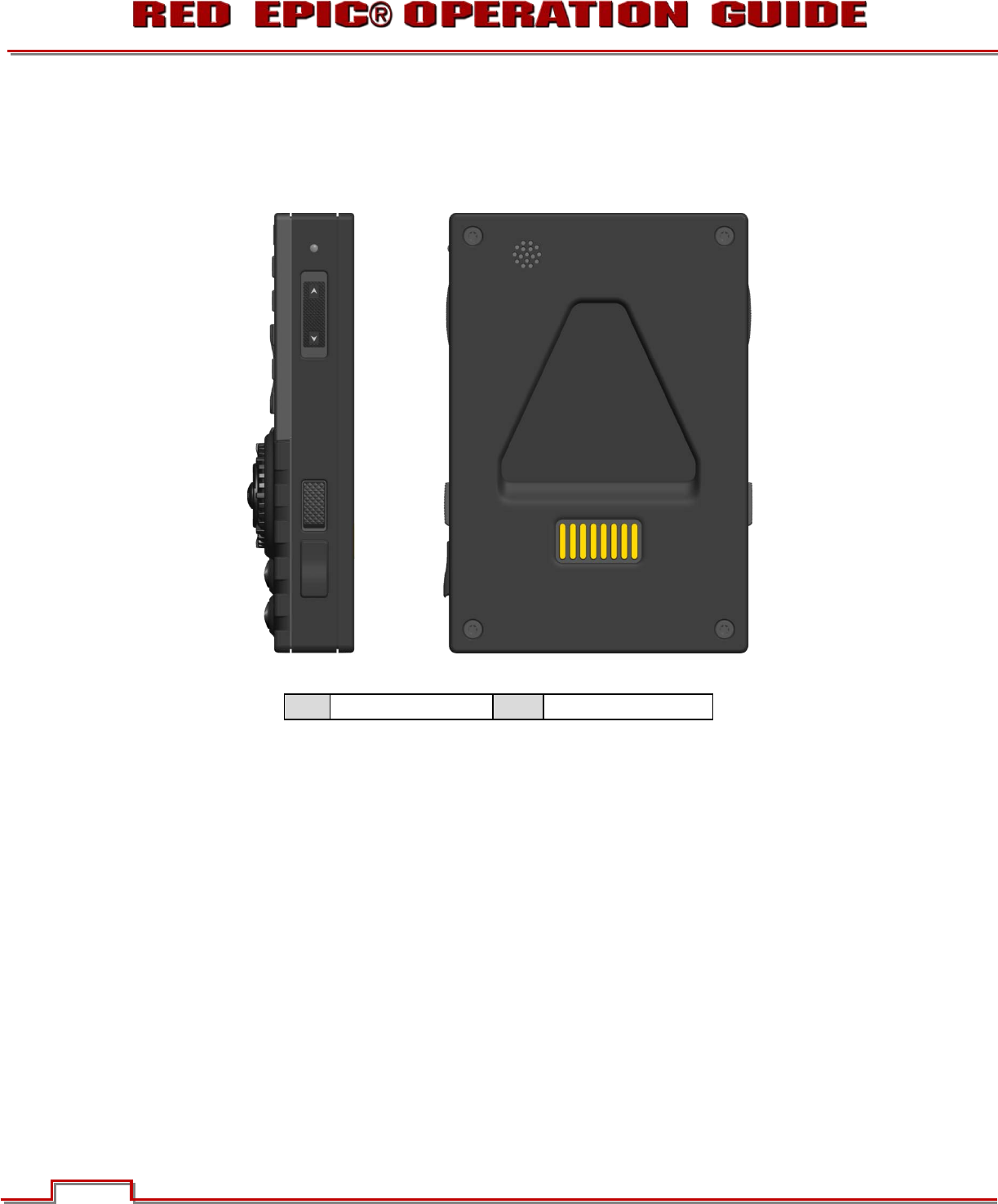
This section describes the physical connectors on the REDmote.
A
Mini USB
B Camera Interface
Figure 27: REDmote Connections
The Mini USB connector (A) may be used to charge the REDmote from a 3
rd
party USB power source.
The REDmote interface connector (B) allows communication between the REDmote and the EPIC or
SCARLET Brain or any expansion module when installed. Make sure these contacts are kept clean and
free of any grease that may interfere with electrical contact.
A
B