
Operation Manual
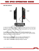
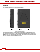
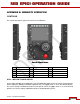
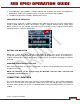
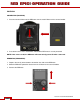
Table Of Contents
- RED EPIC® OPERATION GUIDE
- TABLE OF CONTENTS
- DISCLAIMER
- COMPLIANCE
- BEFORE YOU START
- THEORY OF OPERATION
- CAMERA OPERATIONAL CONTROLS
- BASIC OPERATION
- FIRST TIME USE – SETTING UP YOUR RED EPIC
- MENU CONTROLS
- MAIN MENU
- SECONDARY MENUS
- APPENDIX A: UPGRADING CAMERA FIRMWARE
- APPENDIX B: MANAGING DIGITAL MEDIA
- APPENDIX C: CHARGING BATTERIES
- APPENDIX D: INPUT / OUTPUT CONNECTORS
- APPENDIX E: REDMOTE OPERATION
- APPENDIX F: 3D SETUP / OPERATION
- APPENDIX G: EXPOSURE – USING FALSE COLOR AND ISO
- APPENDIX H: POST PRODUCTION
- APPENDIX I: TROUBLESHOOTING
- APPENDIX J: MAINTENANCE
- APPENDIX K: TECHNICAL DATA
- APPENDIX L: MENU MAPS
Version 1.4.0 SVN 29352 BETA
APRIL 19, 2011 ©2011 RED.COM INC.
131
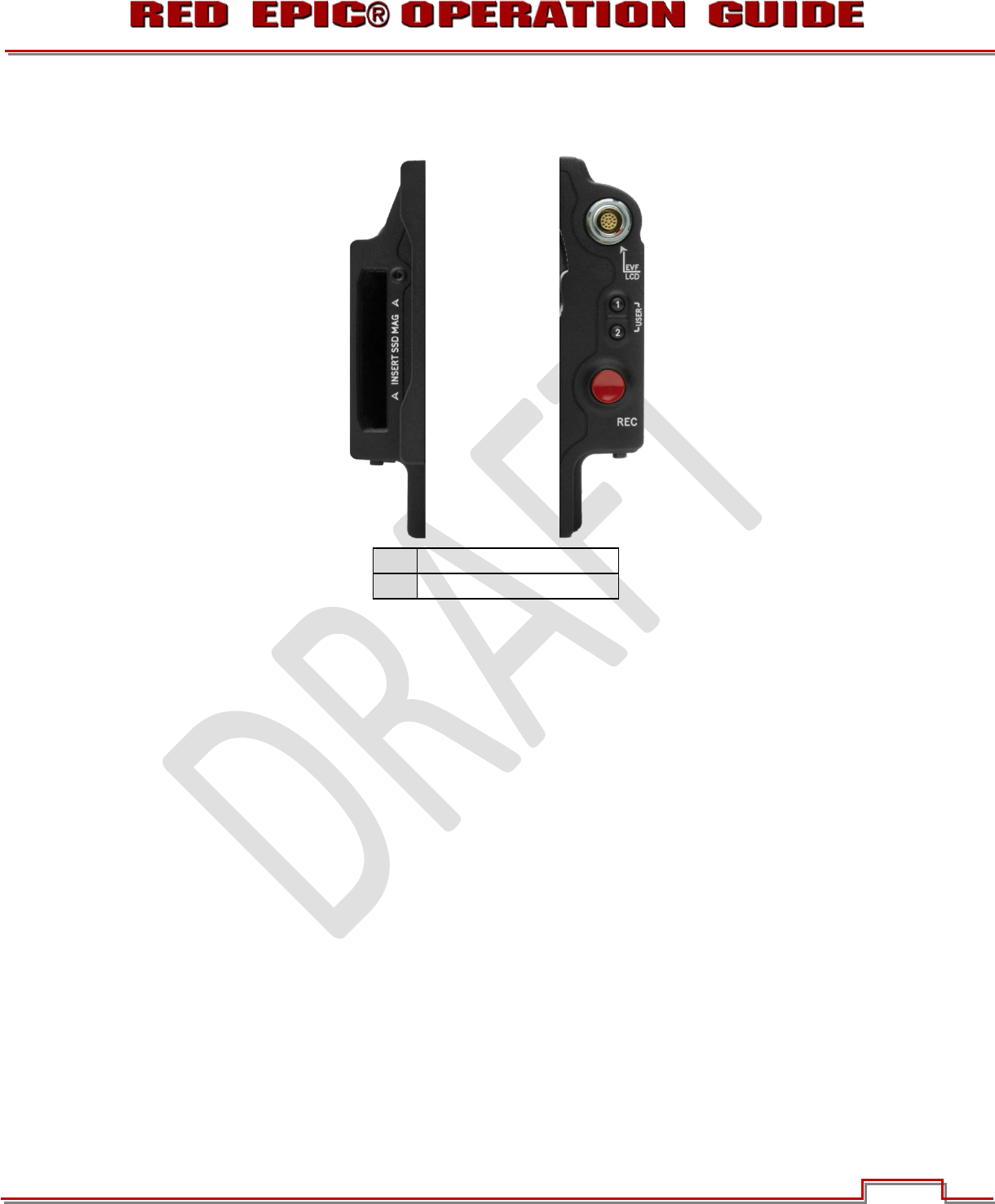
SIDE SSD MODULE
A
SSD Slot
B
VIEWFINDER (LCD/EVF)
Figure 26: Side SSD Module
An optional Side SSD Module may be mounted on the left side of the camera Brian. On the rear face of
this module is a slot for inserting REDMAG 1.8”SSD media. Do not attempt o insert any other media
type, or any foreign objects into this slot, or damage to the Side SSD Module and / or the camera Brain
may occur.
The VIEWFINDER output Module o the front face of the Side SSD provides digital video,
communications and power interconnection between the camera and a RED EVF or RED LCD digital
display. Due to the requirement for absolute data integrity this requires a custom cable manufactured
by RED, the pin-out of this interface is not published.
NOTE: Pre-fabricated VIEWFINDER cables are available from RED Digital Cinema.
x Part # 140-0120 - VIEWFINDER – Right Angle to Right Angle - 6in (0.15m)
x Part # 140-0177 - VIEWFINDER – Right Angle to Straight- 18 in (0.5m)
A
B
FRONT
REAR