
Operation Manual
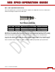

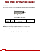

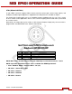

Table Of Contents
- RED EPIC® OPERATION GUIDE
- TABLE OF CONTENTS
- DISCLAIMER
- COMPLIANCE
- BEFORE YOU START
- THEORY OF OPERATION
- CAMERA OPERATIONAL CONTROLS
- BASIC OPERATION
- FIRST TIME USE – SETTING UP YOUR RED EPIC
- MENU CONTROLS
- MAIN MENU
- SECONDARY MENUS
- APPENDIX A: UPGRADING CAMERA FIRMWARE
- APPENDIX B: MANAGING DIGITAL MEDIA
- APPENDIX C: CHARGING BATTERIES
- APPENDIX D: INPUT / OUTPUT CONNECTORS
- APPENDIX E: REDMOTE OPERATION
- APPENDIX F: 3D SETUP / OPERATION
- APPENDIX G: EXPOSURE – USING FALSE COLOR AND ISO
- APPENDIX H: POST PRODUCTION
- APPENDIX I: TROUBLESHOOTING
- APPENDIX J: MAINTENANCE
- APPENDIX K: TECHNICAL DATA
- APPENDIX L: MENU MAPS

Version 1.4.0 SVN 29352 BETA
APRIL 19, 2011 ©2011 RED.COM INC.
121
MIC-1, MIC-2 (MICROPHONE AUDIO)
Two 3.5mm phone jacks on the front of the brain support two independent channels of balanced or
unbalanced analog microphone level audio inputs.
Figure 19: Microphone Input Connector
Pin Signal Description Direction
A (TIP)
IN + Mic Input (+48V Phantom Power) In
B (RING)
IN - Mic Input (+48V Phantom Power) In
C (SLEEVE)
GND Camera ground --
Microphone Level analog audio input signals are routed via a high quality A/D and pre-amplifier, whose
Gain may be controlled using the Input Level control to achieve the desired audio reference / recording
level. Each microphone input supports +48V @ 10mA Phantom Power as a user selectable option.
To assist with reference level setup, the camera provides a color-coded Peak Level Meter in the
Graphical User Interface, with a solid vertical witness mark that indicates 0dBu / 0.775 v RMS /-20dbFS.
Peak Level Meter range is –34dBu to +20dBu (-54dBFS to 0dBFS) and provides input clip indication.
A
B
C