
Manual


RED DSMC POWER OPERATION GUIDE
COPYRIGHT © 2014 RED.COM, INC
955-0038, REV-F | 29
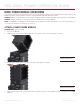
CHARGE IN
Use the 6-pin 1B LEMO CHARGE IN port to charge batteries and provide power to the AUX POWER OUT port.
6
5
4
3
2
1
6-PIN 1B LEMO CHARGE IN CONNECTOR
1
PIN SIGNAL DESCRIPTION
1 +VBATT Power input, +11.5 to +17 V DC
2 +VBATT N/A
3 SCL-BATT Serial Battery Bus Clock
4 GROUND Power Return (Camera Ground)
5 GROUND N/A
6 SCA-BATT Serial Battery Bus Data
1. Mating connector: FGJ.1B.306.CWLD72Z
COMPATIBLE CABLES
790-0138: 2B-to-1B LEMO Power Adaptor Cable
790-0164: XLR Power Cable (10')
790-0165: XLR Power Cable (30')
REDVOLT XL MODULE INDICATOR LEDS
The REDVOLT XL Module indicator LEDs display information about the current state of an equipped REDVOLT
XL Battery when the module is being used as a desktop charging station. Refer to the following table for infor-
mation about the different REDVOLT XL charging states.
COLOR/FLASHING DESCRIPTION
Green flashing Charging; half second on, half second off
Green solid Battery is fully charged
Red/Green flashing (alternating) Error; alternating, half second green, half second red, repeat
Red/Green flash Lamp self test at power up; half second red, half second green
Red flashing (pulsing) Battery discharge alert; heartbeat (red) pulse once per minute
indicates that the battery is discharging and should be re-
moved from module
1
1. The REDVOLT XL Module draws a small amount of power any time a battery is attached, when there is no charging source available.
CHARGE IN Connector