
User's Manual

V7 EXTERNAL ANTENNA RTLS MODULE USER MANUAL
© 2020 Redpoint Positioning Corp. Restricted Distribution 7
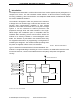
3.2.1. Reset
The module can be reset externally by driving the nRST_i pin low for at least 0.5us. nRST_i is
internally pulled up and no external pull-up is necessary.
During bootup, the module will drive nRST_o low for at least 10ms. Once the module is
operational, the nRST_o will be tri-stated. Note that nRST_o is only asserted after nRST_i is
de-asserted.
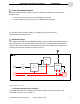
3.2.2. External Power Source Mode
The module reads EXT_PWR to determine if there is an unlimited external power source. If
EXT_PWR is pulled up, the device is considered externally powered and operates in a high-
current consumption mode. If EXT_PWR is not connected or pulled down, the device is
considered battery-powered. EXT_PWR is connected to an internal 13K pull-down resistor, so
the external driver should provide at least 160uA to pull up the EXT_PWR reliability.
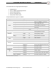
3.2.3. UART
The UART is the full duplex bi-directional serial interface and the primary communication
channel between the module and the external host or slave devices (e.g., host processor,
display controller, etc.). To communicate to the module through UART, the interface shall be
configured as follows:
Baud Rate 115,200
Flow Control None
Data format 8 bit
Parity None
Stop 1 bit
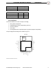
3.2.4. Configurable IOs
There are 5 multi-purpose pins that can be configured as GPIOs or special purpose pins. The
configurations of these IOs are defined by the CFG register (see details in 3.2.4.2). When
configured as special purpose IOs, these pins can be used as:
I
2
C bus: only supports the peripherals verified by RPP
Alarm output: user alarm output, active low
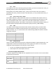
3.3. Power Supply Requirements
The power supplies for the UWB radio are separated from the rest of the circuit on the module
to improve the performance.
Power Rail Parameter Condition Min Typ Max Unit
VCC_UWB
Voltage 2.8 3.3 3.6 V
Current @3.3V - 145 mA
VCC
Voltage 2.8 3.3 3.6 V
Current @3.3V - 12 mA
TABLE 4. POWER INPUT REQUIREMENTS