
User's Manual

V7 EXTERNAL ANTENNA RTLS MODULE USER MANUAL
© 2020 Redpoint Positioning Corp. Restricted Distribution 6
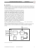
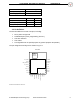
The external IOs can be grouped functionally as:
Dedicated pins
One (1) SWD programming interface
One (1) UART interface
Five (5) configurable IOs
One (1) NFC antenna port
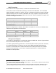
The pin definitions are given in Table 3.
Category Pin name Type Pin Description
Power
VCC
power input 8, 16 2.8V-3.6V
VCC_UWB
power input 1
Power for UWB RF, must be the
same voltage with VCC
nRST_o
output 6
Open drain reset output, needs
external pull-up, active low.
EXT_PWR
input 4
External power source mode,
active high
GND ground
2,5,7,9,10,
15,17
Power ground
Programming
Interface
SWDCLK
input 23
SWD programming interface with
internal pull-down resistor
SWDIO
input /
output
24
SWD programming interface with
internal pull-up resistor
nRST_i
input 22
Reset input with 13KOhm internal
pull-up resistor, active low
UART
TXD
output 20 UART interface
RXD
input
21
UART interface
NFC RF
NFC1
RF 18 NFC antenna port
NFC2
RF 19 NFC antenna port
Configurable
multipurpose
IOs
SDA / GPIO(0)
digital IO /
analog in
11
I2C bus with 13KOhm internal pull-
up resistor / GPIO
SCL / GPIO(1)
digital IO /
analog in
12
I2C bus with 13KOhm internal pull-
up resistor / GPIO
INT / GPIO(2)
digital IO /
analog in
13
IRQ input with internal pull-up
resistor / GPIO
nALM_o / GPIO(3)
digital IO /
analog in
14
Open drain alarm output, tri-state
in inactive mode, active low / GPIO
nALM_i / GPIO(4)
digital IO /
analog in
3
User alarm input with internal pull-
up resistor, active low / GPIO
TABLE 3. PIN DEFINITION AND DESCRIPTION