V7 External Antenna RTLS Module User Manual Version 1.6 © 2020 Redpoint Positioning Corp.
V7 EXTERNAL ANTENNA RTLS MODULE USER MANUAL Table of Contents Introduction.................................................................................................................... 3 Partner Branding Guidelines ........................................................................................... 4 Hardware Design ............................................................................................................ 4 3.1. Storage and Operating Conditions ..............................
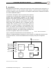
V7 EXTERNAL ANTENNA RTLS MODULE USER MANUAL Introduction The Redpoint RTLS Module is a full-function Real-Time Location System (RTLS) subsystem in a compact form factor. The self-contained module delivers all RTLS functions including highaccuracy positioning, data communication over Redpoint UWB network, and Bluetooth without the need of additional hardware.
V7 EXTERNAL ANTENNA RTLS MODULE USER MANUAL Partner Branding Guidelines Redpoint Positioning Corp. requires all partner companies to display the ‘Positioned by Redpoint’ logo: On your software UI if you access the Redpoint server API On the outside of your tag if you use the Redpoint RTLS module For questions about partner branding, or to obtain the logo, please contact support@redpointpositioning.com.
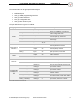
V7 EXTERNAL ANTENNA RTLS MODULE Parameter Maximum Rating Temperature (°C) Humidity (%) -40 to 85 < 95 USER MANUAL TABLE 1. STORAGE CONDITIONS Parameter Temperature (°C) Humidity (%) Supply Voltage (V) Min -40 N/A 2.8 Max 85 <90 3.6 TABLE 2. OPERATING CONDITIONS 3.2. Pin Definition The RTLS module has a total of 24 pins, including: 10 for power and ground 5 dedicated pins (reset, programming, and etc.
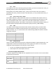
V7 EXTERNAL ANTENNA RTLS MODULE USER MANUAL The external IOs can be grouped functionally as: Dedicated pins One (1) SWD programming interface One (1) UART interface Five (5) configurable IOs One (1) NFC antenna port The pin definitions are given in Table 3. Category Power Programming Interface Pin name Type Pin Description VCC power input 8, 16 2.8V-3.
V7 EXTERNAL ANTENNA RTLS MODULE USER MANUAL 3.2.1. Reset The module can be reset externally by driving the nRST_i pin low for at least 0.5us. nRST_i is internally pulled up and no external pull-up is necessary. During bootup, the module will drive nRST_o low for at least 10ms. Once the module is operational, the nRST_o will be tri-stated. Note that nRST_o is only asserted after nRST_i is de-asserted. 3.2.2.
V7 EXTERNAL ANTENNA RTLS MODULE USER MANUAL 3.4. RF Transceiver The module has two complete radios, the UWB and the Bluetooth® radio. The module contains a UWB radio operating in the unlicensed UWB band. The transmitted signal bandwidth is 500 MHz or greater. The unit is calibrated such that the maximum radiated spectrum density does not exceed -41 dBm/MHz and is fully compliant to the spectrum mask defined in FCC part 15.
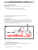
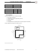
V7 EXTERNAL ANTENNA RTLS MODULE USER MANUAL FIGURE 5. MODULE LAND PATTERN 3.6. Reference Design Figure 6. Reference Design © 2020 Redpoint Positioning Corp.
V7 EXTERNAL ANTENNA RTLS MODULE USER MANUAL 3.7. Packaging and Handling The dimensions of the module are 32mm(L) x 25mm(W) x 3.11mm(T). There are 24 castellation hole pin-outs around the module. The pitch is 100mil (2.54mm). FIGURE 7. DIMENSION OF RTLS MODULE 3.8. Recommend Reflow Soldering Profile FIGURE 8. RECOMMEND PB-FREE REFLOW SOLDERING PROFILE © 2020 Redpoint Positioning Corp.
V7 EXTERNAL ANTENNA RTLS MODULE USER MANUAL 3.9. Certification and Marking The RTLS module is certified for the following countries and regions: Country or Region (Certification Authority) USA (FCC) Canada (IC) European Union China, including Hong Kong (CMIIT) ID or Marking 2ADX4-MODV7 12677-MODV7 CE marking for emission, safety and environmental TABLE 7.
V7 EXTERNAL ANTENNA RTLS MODULE USER MANUAL The RTLS module supports communication over UART interfaces. 4.2.1. UART Interface The UART is the full duplex bi-directional interface between the module and the external host device. The following is the physical configuration of the UART: Baud rate: 115200. No hardware flow control. 8N1 byte format. 4.2.1.1. UART Modes of Operation The module’s UART has two modes of operation, command and binary.
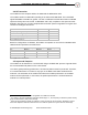
V7 EXTERNAL ANTENNA RTLS MODULE Name Type Values USER MANUAL Description z int32 Position Z in mm. sl uint16 Area ID fom uint8 er uint32 op string ts uint32 50-255 Figure of merit—confidence level of the position estimate. A smaller value is better. Note: Not available for 1D, 0D and PD positioning mode. 0D mode - distance to 0D anchor in mm. 1D mode – distance to the line connecting anchor pair(mm). Note: Only available in 0D and 1D modes.
V7 EXTERNAL ANTENNA RTLS MODULE Name Type md uint8 USER MANUAL Description 0 - no motion detected / 1 - motion detected TABLE 10 CONTENT FIELDS OF THE IMU MESSAGE. The following is an example of the IMU raw readings: #IMU ax=ddddd ay=ddddd az=ddddd rx=bbbbb ry=bbbbb rz=bbbb ts=45376 md=1 4.2.2.3. #ALM – Alarm Alarm messages start with the preamble #ALM and have the following content fields: Name Type Values Description t string SA|CA Alarm type.
V7 EXTERNAL ANTENNA RTLS MODULE USER MANUAL Note: When the alarm message is sent, the nALM_o is also driven low if special purpose nALM_o is configured using CFG command. 4.2.2.4. #MSG – Server message ASCII messages received from the server are issued from the module as #MSG messages. This message type is indicated with the preamble #MSG, followed by the actual ASCII strings of the message. The preamble and the body of the server message is separated by a space.
V7 EXTERNAL ANTENNA RTLS MODULE Name Type USER MANUAL Description sn string MAC address of the module. hw string Hardware revision of the module. cbid string Carrier board ID. fw string Firmware version. TABLE 13 VERSION MESSAGE CONTENT FIELDS The following is an example of the #VER message: #VER sn=E4956EAE01BB hw=7.0 cbid=3E61 fw=5.7.1 The module will print version messages at bootup automatically if the “Keep CMD on” flag is set. 4.2.3.
V7 EXTERNAL ANTENNA RTLS MODULE USER MANUAL CFG config_word where config_word is a 32bit hexadecimal value (reset value is 0xA0000000). The ‘0x’ prefix is not required. If the command is sent without the value field, it is treated as a read command and the module will output the configuration value.
V7 EXTERNAL ANTENNA RTLS MODULE USER MANUAL Note: The local pos output at tag UART (CFG OUT en=P) may not be matched with the pos updates sent to server when AF (Advance Filtering) is enabled on tag. Please refer to 3.2.4.4 CFG IMU for more details. When AF is enabled, the pos update could be sent from AF with IMU data. The local pos output (CFG OUT en=P) could be mismatched with the pos data sent to server.
V7 EXTERNAL ANTENNA RTLS MODULE USER MANUAL 4.2.3.6. CFG CBD The CFG CBD message is used to check and set the CBID and has the following fields: Name Type Values Description id string null <4 character string value> The ID can only be set once. Redpoint will assign a CBID based on the carrier board with which the RTLS module is embedded.
V7 EXTERNAL ANTENNA RTLS MODULE USER MANUAL 4.2.3.9. Version Upon receiving the following command, the module will print out the HW and SW versions. VER See 4.2.2.5 for details. 4.2.3.10. BAT - External battery remaining capacity The BAT command provides an interface to set the value of the remaining external battery capacity. It reports to the server as a battery level. If it is issued without arguments, the module will print the current value.
V7 EXTERNAL ANTENNA RTLS MODULE Name Type Values USER MANUAL Description Requesting OTA control: host string off on on – host requesting OTA control off – host cancels OTA control In the following examples, H is the host MCU and M is the RPP module. The following is an example of a CFG OTA message. The Host is requesting OTA control and the module accepts the request: 1. H M CFG OTA host=on 2. M H #CFG OTA host=on The following is an example of a CFG OTA message.
V7 EXTERNAL ANTENNA RTLS MODULE Name Type Values Description status string USER MANUAL on off on – OTA process is on-going, variables “completed” and “size” indicates completion percentage and size of the FW image off –OTA process is terminated/completed Variable indicates completion of the OTA process in percent.
V7 EXTERNAL ANTENNA RTLS MODULE USER MANUAL OTA started, host allowed to proceed: MH #OTA status=on completed=1 size=256000 OTA started, host canceled operation: 1. M H #OTA status=on completed=1 size=256000 2. H M OTA cmd=cancel 3. M H #OTA status=off OTA periodic reporting: MH #OTA status=on completed=57 size=256000 OTA status check requested by host: 1. H M OTA cmd=status 2. M H: #OTA status=on completed=57 size=256000 or 1. H M : © 2020 Redpoint Positioning Corp.
V7 EXTERNAL ANTENNA RTLS MODULE USER MANUAL OTA cmd=status 2. M H: #OTA status=off 4.3.2. SWD interface In the case that the OTA firmware update is impractical, the update can be performed via the SWD (Serial Wire Debug) programming interface. SWD is a two-wire protocol for accessing the ARM debug interface. It is part of the ARM Debug Interface Specification v5 and is an alternative to JTAG. Please refer to reference [2] for more details. Regulatory Information 5.1.
V7 EXTERNAL ANTENNA RTLS MODULE USER MANUAL 2) this device must accept any interference received, including interference that may cause undesired operation. 5.5. ISED RSS-Gen Notice (in English and French): This device complies with Industry Canada’s licence-exempt RSSs. Operation is subject to the following two conditions: 1) This device may not cause interference; and 2) This device must accept any interference, including interference that may cause undesired operation of the device.
V7 EXTERNAL ANTENNA RTLS MODULE USER MANUAL 7) Additional testing, Part 15 Subpart B disclaimer - include a statement that the final host product still requires Part 15B compliance testing with the modular transmitter installed Disclaimer: The information provided in this document is subject to change without notice. © 2020 Redpoint Positioning Corp.