
User Manual
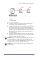
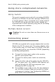
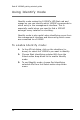
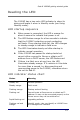
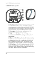

Table Of Contents
- Table of contents
- Introduction
- Mounting the 1000AP
- Figure 1: Mounting the 1000AP to a ceiling or wall
- To mount on a ceiling or wall:
- 1. Select a location on a ceiling or wall to mount the 1000AP (we recommend mounting on a ceiling).
- 2. Ensure the ceiling or wall can support the 1000AP’s weight (around 250 g or 8.5 oz). If in dou...
- 3. Install the Category 5 Ethernet cable according to whether you decided to ‘star-wire’ or ‘dais...
- 4. Use the mounting bracket as a template to mark out drill positions.
- 5. Drill two holes (43 mm apart) using a 5.5 mm drill bit. Ensure the two holes are vertically al...
- 6. Insert suitable fastenings into the holes (e.g. wall plugs).
- 7. Position the mounting bracket over the two holes and insert the appropriate screws.
- 8. Connect the cables from the hole in the ceiling/wall to the 1000AP.
- 9. Slide the 1000AP over the mounting bracket until it fits into the groove. Continue sliding unt...
- Connecting the cables
- Star-wiring from a 3000AS
- Star-wiring from a Linux server
- Daisy-chaining
- Figure 3: Daisy-chain installation
- 1. Connect a Category 5 Ethernet cable (with RJ-45 connectors) to the 1000AP’s IN port.
- 2. Connect the other end of the cable to the 3000AS’s blue Access Point port or purple Office LAN...
- 3. Connect the first 1000AP’s OUT port to the second 1000AP’s IN port. Ensure there is no more th...
- Using more complicated networks
- Connecting power
- 1. Connect the loose power cable to the country- specific mains power lead.
- 2. Connect the mains power lead to an electricity supply.
- 3. Insert the other end of the cable into the 1000AP’s DC 12v power port. The 1000AP’s LED indica...
- 4. The 1000AP is now ready to use. You can configure the 1000AP’s software features through the G...
- Configuring 1000APs
- To edit the 1000AP’s configuration
- 1. Log on to the management interface as an administrator from a management PC.
- 2. The AP List dialog displays with all connected access points. If a 1000AP is missing from this...
- 3. Click on a 1000AP’s name or hardware address to open the AP Stats dialog, which shows informat...
- 4. Click on AP Record to open the Bluetooth AP Edit dialog. In this dialog, you can rename the 10...
- To edit the 1000AP’s configuration
- Using Identify mode
- Reading the LED
- LED startup sequence
- 1. When power is connected, the LED is orange for about a second to indicate that power is on.
- 2. The LED flashes orange for a few seconds to indicate that the 1000AP is starting up and conduc...
- 3. The LED illuminates steady red after startup to indicate normal operation.
- 4. If the 1000AP has passed its startup tests but cannot either connect to Genos or obtain an IP ...
- 5. If there is a fatal error at any time, the LED illuminates steady orange. If it remains in thi...
- LED indicator status chart
- LED startup sequence
- 1000AP diagram
- Contact information
- Regulatory information
- The following regulatory statements apply to the Red-M 1000AP access point.
- By attaching themark to this product, we confirm:
- To conform with FCC rules regarding RF exposure, this equipment should be installed a minimum of ...
- Any changes or modifications not expressly approved by the manufacturer could void the user’s aut...
- This device has been designed to operate with an antenna that has a maximum gain of 0 dB. Antenna...
- To reduce potential radio interference to other users, the antenna type and its gain should be so...
- To prevent radio interference to the licensed service in Canada, this device is intended to be op...
- This product is designed to connect to "Bluetooth" compatible radio interfaces using the 2.4 GHz ...
- [Member States of the EEA are: Austria, Belgium, Denmark, Finland, France, Germany, Greece, Icela...
- English
- Dansk
- Deutsch
- Español
- Flemish
- Français
- Íslenska
- Italiano
- Nederlands
- Norsk
- Português
- Suomi
- Svensk

Red-M 1000AP getting started guide
16
1000AP diagram
1. Mounting cavity. Use the mounting cavity to mount
the 1000AP to a wall or ceiling. Attach the supplied
mounting bracket to a flat surface and slide the 1000AP’s
mounting cavity over the bracket to lock it into place. For
more information, see Mounting the 1000AP on page 7.
2. Power port. Use the power port to connect the
supplied DC 12v adapter to the 1000AP.
3. OUT port and indicator. Use the OUT port to
connect another 1000AP if installing in a ‘daisy-chain’
configuration.
4. IN port and indicator. Use the IN port to connect to
the Genos server directly. You may also use it to connect
an Ethernet switch or hub, or to another 1000AP’s OUT
port if installing in a ‘daisy-chain’ configuration. See
Connecting the cables on page 9 for more information.
5. LED indicator. The LED indicator shows the 1000AP’s
status. It is also used to ‘identify’ the 1000AP. See the
sections on Using Identify mode on page 14 and Reading
the LED on page 15 for more information.
1
2
3
4
5