
Instruction Manual


APPENDIX “B” - SPECIFICATIONS AND DIMENSIONS
1. DISPLAY: Dual 4-digit
Upper Temperature Display: 0.4" (10.2 mm) High Red LED
Lower Auxiliary Display: 0.3" (7.6 mm) High Green LED
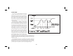
Display Messages:
“OLOL” - Appears when measurement exceeds + sensor range.
“ULUL” - Appears when measurement exceeds - sensor range.
“OPEN” - Appears when open sensor is detected.
“SHrt” - Appears when shorted sensor is detected (RTD only).
“....” - Appears when display value exceeds + display range.
“-...” - Appears when display value exceeds - display range.
2. POWER: Switch selectable 115/230 VAC (+10%, -15%) no observable
line variation effect, 48-62 Hz, 10 VA
3. ANNUNCIATORS:
6 LED Backlight Status Indicators:
%PW - Lower auxiliary display shows power output in (%).
PGM - Lower auxiliary display shows profile status or profile time remaining.
MAN - Controller is in manual mode.
OP1 - Main control output is active.
AL1 - Alarm #1 is active.
AL2 - Alarm #2 is active (For dual alarm option).
OP2 - Cooling output is active (For cooling option).
4. CONTROLS: Four front panel push buttons for setup and modification of
controller functions and one external input.
-72-
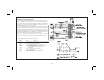
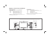
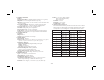
DIMENSIONS In inches (mm)
Note: Recommended minimum clearance (behind the panel) for panel latch installation is 5.5" (140)H x 2.1" (53.4)W.
PANEL CUT-OUT