
Instruction Manual
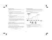


UNPROTECTED PARAMETER MODE
The Unprotected Parameter Mode is accessed by
pressing the PAR button from the normal display mode
with program disable inactive. In this mode, the operator
has access to the list of the most commonly modified
controller parameters. At the end of the list, a
configuration “access point” allows the operator to enter
the configuration parameter modules. These modules
allow access to the fundamental set-up parameters of the
controller. When the program list has been scrolled
through, the controller displays “End” and returns to the
normal display mode. The unit automatically returns to
the normal display mode if a button is not pressed within
eight seconds.
-25-
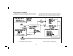
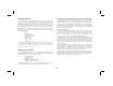
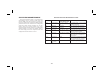
Display Parameter
Range and Units
(Factory Setting Value)
Description/Comments
SP Temperature
Setpoint
Must be within range of limits
SPLO, SPHI 1 or 0.1 degree
(0)
Appears only if setpoint value is locked (LOC) or read
only (rEd). During a profile ramp phase, indicates the
target setpoint value.
OPOF %Output
Power Offset
-99.9% to 100.0%
SPLO, SPHI 1 or 0.1 degree
(0.0)
Appears only if integral time (Intt) = 0 and controller
is in automatic mode.
OP Output Power -99.9% to 100.0%
SPLO, SPHI 1 or 0.1 degree
(0.0)
Appears only if controller is in user (manual) mode
and % output power is locked (LOC) or read only
(rEd). This parameter is not limited to output power
limits (OPL0 & OPHI)
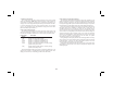
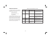
ProP Proportional
Band
0.0 to 999.9% of selected
input range
(4.0)
0.0% is ON/OFF control. If = 0.0%, set control
hysteresis appropriately.
Intt Integral Time 0 to 9999 sec.
(120)
0 is off. This parameter does not appear if
proportional band = 0.0%.
dErt Derivative
Time
0 to 9999 sec.
(30)
0 is off. This parameter does not appear if
proportional band = 0.0%.
AL-1 Alarm 1 Value -999 to 9999 1 or 0.1 degree
(0)
This parameter does not appear if the alarm option is
not installed or is configured as a timed event output.
AL-2 Alarm 2 Value -999 to 9999 1 or 0.1 degree
(0)
This parameter does not appear if the alarm option is
not installed or is configured as a timed event output.
Also does not appear if the cooling option is installed.
CNFP Configuration
Access Point
NO Return to normal display mode.
YES Enter Configuration modules.
1-IN Configure input parameters.
2-OP Configure output parameters.
3-LC Configure parameter lockouts.
4-AL Configure alarms (optional)
5-02 Configure cooling output (optional)
6-SC Configure serial communications (optional)
7-CP Configure control points
8-PR Configure profiles
9-FS Factory service operations (Qualified technicians
only)
End Unit returns to
normal display
mode.
— Brief display message
Unprotected Parameter Mode Reference Table