tscCOVR-b.
tscCOVR-b.QXD 5/2/05 2:48 PM Page 2 INTRODUCTION The Temperature Setpoint Controller Unit (TSC) is a multi-purpose series of industrial control products that are field-programmable for solving various applications. This series of products is built around the concept that the end user has the capability to program different personalities and functions into the unit in order to adapt to different indication and control requirements.
Table of Contents GENERAL DESCRIPTION · · · · · · · · · · · · · · · · · · · · · · · · · · · · · · · · · · · · · · · · · · · · · · · · · · · · · · · · · · · · · 6 Safety Summary · · · · · · · · · · · · · · · · · · · · · · · · · · · · · · · · · · · · · · · · · · · · · · · · · · · · · · · · · · · · · · · · · · · 7 INSTALLATION & CONNECTIONS · · · · · · · · · · · · · · · · · · · · · · · · · · · · · · · · · · · · · · · · · · · · · · · · · · · · · 7 Installation Environment · · · · · · · · · · · · · · · · · · ·
Pause Mode · · · · · · · · · · · · · · · · · · · · · · · · · · · · · · · · · · · · · · · · · · · · · · · · · · · · · · · · · · · · · · · · · · 16 Delay Mode · · · · · · · · · · · · · · · · · · · · · · · · · · · · · · · · · · · · · · · · · · · · · · · · · · · · · · · · · · · · · · · · · · · 17 Controlling A Profile · · · · · · · · · · · · · · · · · · · · · · · · · · · · · · · · · · · · · · · · · · · · · · · · · · · · · · · · · · · · · · · 18 Profile Start Operation · · · · · · · · · · · · · · · · · · · · · ·
Normal Display Mode · · · · · · · · · · · · · · · · · · · · · · · · · · · · · · · · · · · · · · · · · · · · · · · · · · · · · · · · · · · · · 23 Modifying A Secondary Display Parameter From The Front Panel · · · · · · · · · · · · · · · · · · · · · · 23 Setpoint Value Display · · · · · · · · · · · · · · · · · · · · · · · · · · · · · · · · · · · · · · · · · · · · · · · · · · · · · · · · 23 % Output Power Display · · · · · · · · · · · · · · · · · · · · · · · · · · · · · · · · · · · · · · · · · · · · · · · · ·
Hidden Mode Lockouts (ALrS, CPAC, PrAC, trnF, & tUNE) · · · · · · · · · · · · · · · · · · · · · · · · · · · · 34 Alarm Module (4-AL) (Optional) · · · · · · · · · · · · · · · · · · · · · · · · · · · · · · · · · · · · · · · · · · · · · · · · · · · · · 35 Alarm Action (Act1, Act2) · · · · · · · · · · · · · · · · · · · · · · · · · · · · · · · · · · · · · · · · · · · · · · · · · · · · · · · 35 Alarm Reset (rSt1, rSt2) · · · · · · · · · · · · · · · · · · · · · · · · · · · · · · · · · · · · · · · · · · · · · · · ·
RS-485 SERIAL COMMUNICATIONS INTERFACE · · · · · · · · · · · · · · · · · · · · · · · · · · · · · · · · · · · · · · · 58 Communication Format · · · · · · · · · · · · · · · · · · · · · · · · · · · · · · · · · · · · · · · · · · · · · · · · · · · · · · · · · · · · 58 Sending Commands And Data · · · · · · · · · · · · · · · · · · · · · · · · · · · · · · · · · · · · · · · · · · · · · · · · · · · · · · 58 Receiving Data · · · · · · · · · · · · · · · · · · · · · · · · · · · · · · · · · · · · · · · · · · · · · · · ·
GENERAL DESCRIPTION The optional RS-485 multidrop serial communications interface provides the capability of two-way communication between a TSC unit and other compatible equipment such as a printer, a programmable controller, or a host computer. In multipoint applications the address number of each unit on the line can be programmed from 0-99. Up to thirty two units can be installed on a single pair of wires. The Setpoint value, % Output Power, Setpoint Ramp Rate, etc.
INSTALLATION & CONNECTIONS SAFETY SUMMARY All safety related regulations, local codes and instructions that appear in the manual or on equipment must be observed to ensure personal safety and to prevent damage to either the instrument or equipment connected to it. If equipment is used in a manner not specified by the manufacturer, the protection provided by the equipment may be impaired. Do not use the TSC to directly command motors, valves, or other actuators not equipped with safeguards.
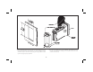
PANEL INSTALLATION & REMOVAL Note: Prior to applying power to the controller, the internal AC power selector switch must be set. Damage to the controller may occur if the switch is set incorrectly. Note: The installation location of the controller is important. Be sure to keep it away from heat sources (ovens, furnaces, etc.), away from direct contact with caustic vapors, oils, steam, or any other process by-products in which exposure may effect proper operation.
UNIT REMOVAL PROCEDURE To remove a NEMA 4X/IP65 or standard unit from the panel, first unscrew and remove the panel latch screws. Insert flat blade screwdrivers between the latch and the case on the top and bottom of the unit so that the latches disengage from the grooves in the case. Push the unit through the panel from the rear.
OUTPUT MODULES The main control, optional alarm, and optional cooling output sockets must be fitted with the appropriate output module. Output modules are shipped separately and must be installed by the user. Output Variations Without RS-485 Option The Dual Alarm or the Cooling with Alarm output, without the RS-485 option, has independent outputs. Therefore, the cooling output and/or alarm output(s) can be installed with any combination of output modules.
SELECT INPUT SENSOR TYPE The input sensor type (thermocouple or RTD) must be selected by an internal hardware jumper to match the input sensor type programmed. The jumper is located inside the case on a small accessory circuit board near the rear of the unit on the main circuit board (See hardware selection figure and/or label on outside of case). Logic/SSR Drive: Type: Non-isolated switched DC, 12 VDC typ. (internal 500 W resistance). Drive: 10 mA max. (400 ohm external load).
SELECT AC POWER (115/230 VAC) The AC power to the unit must be selected for either 115 VAC or 230 VAC. The selector switch is located inside the case near the rear of the unit on the main circuit board (See hardware figure and/or label on inside or outside of case). The unit is shipped from the factory with the switch in the 230 VAC position. Note: Damage to the controller may occur if the AC selector switch is set incorrectly.
Signal Wiring When connecting the thermocouple or RTD leads, be certain that the connections are clean and tight. If the thermocouple probe cannot be connected directly to the controller, thermocouple wire or thermocouple extension-grade wire must be used to extend the connection points (copper wire will not work). Always refer to the thermocouple manufacturer’s recommendations for mounting, temperature range, shielding, etc.
FRONT PANEL DESCRIPTION The front panel bezel material is flame and scratch resistant tinted plastic. Available is an optional NEMA 4X/IP65 version which has a bezel that meets NEMA 4X/IP65 requirements, when properly installed. There are two 4-digit LED displays, a red upper Main Display and a lower green Secondary Display. There are up to six annunciators depending on options installed, with red backlighting, which illuminate to inform the operator of the controller and output status.
OPERATION OVERVIEW CONTROLLER POWER-UP Upon applying power, the controller delays control action and temperature indication for five seconds to perform several self-diagnostic tests and displays basic controller information. Initially, the controller illuminates both displays and all annunciators to verify that all display elements are functioning. Following, the controller displays the programmed input sensor type in the Main display (verify that the input select sensor jumper matches the programming).
PROFILE OPERATING MODES Run Mode The controller is in the Run Mode when a profile is executing. While in the Run Mode, the profile can be stopped (Off Mode), paused (Pause Mode) or advanced to the next phase. A profile is started and placed into the Run Mode either manually or automatically when the controller is powered-up. The advancement of the profile can be viewed in the secondary display. Off Mode The Off Mode signifies that all profiles are dormant.
Delay Mode The Delay Mode signifies that a profile is active but the time base, or profile advancement is stopped. This is caused by automatic action of the controller when the input temperature deviates more than a specified amount from the profile setpoint. The Delay Mode is similar to the pause mode, except the delay mode is invoked automatically by the controller. The Profile Deviation Error Band programmed for a positive value, allows the Delay Mode to be invoked only during hold phases.
CONTROLLING A PROFILE Profile Start Operation A profile always starts at the first ramp phase and the setpoint value ramps from the current temperature value. The profile can be programmed to ramp from a known setpoint value (see Ramp Phase section). Link-started profiles use the last target setpoint level as the starting point. A profile is started from the off mode, which places the controller into the run mode. To re-start a running profile from the beginning, it is necessary to first stop the profile.
Profile Stop Operation Stopping a profile places the controller into the off mode. When a profile is stopped, the active setpoint value is the old profile setpoint value. Stop Operation From The Profile Control Status Display 1. Verify the profile control status display (P-CS) is enabled in lockout programming. 2. Press and hold the “up/down” buttons simultaneously for three seconds. 3. “OFF” appears in the secondary display and the profile is placed in the off mode.
Advance Operation From The Hidden Mode 1. Verify profile access (PrAC) in the hidden mode is enabled in lockout programming. 2. Press and hold the “PAR” button for three seconds to enter the hidden mode. 3. Scroll to “Prun” (if necessary) by pressing the “PAR” button. 4. When “Prun” is displayed, use the “up/down” buttons to select advance (Adnc). 5. Press the “PAR” button to advance the profile to the next phase. 6.
Continue Operation From The Hidden Mode 1. Verify profile access (PrAC) in the hidden mode is enabled in lockout programming. 2. Unit must be in the pause mode. 3. Press and hold the “PAR” button for three seconds to enter the hidden mode. 4. Scroll to “Prun” (if necessary) by pressing the “PAR” button. 5. When “Prun” is displayed, use the “up/down” buttons to select continue (Cont). 6. Press the “PAR” button to continue the profile. 7.
CONFIGURATION OF PARAMETERS As supplied from the factory, the controller parameters have been programmed to the values listed in the Quick Reference Tables. The user must modify the values, if necessary, to suit the application. S These parameters may not appear due to unit configuration or programming set-ups.
PARAMETER ENTRY The PAR button is used to select the desired parameter. To modify the parameter setting use the UP and DOWN buttons, and then press PAR to enter the new value, the controller progresses to the next parameter. In a Configuration Parameter Module, pressing the DSP button causes the new value to be rejected, the controller displays “End”, and returns to the Normal Display Mode.
% Output Power Display The % output power can only be changed when the unit is in the manual mode. The annunciator %PW lights when viewed, then use the up and down arrow buttons to modify the % output power (if not locked). If locked, the % output power can be changed in the unprotected or protected mode when “OP” is viewed, independent of viewing in the secondary display. The % output power is not constrained to the programmable output power limit values (OPLO & OPHI, output module 2).
UNPROTECTED PARAMETER MODE The Unprotected Parameter Mode is accessed by pressing the PAR button from the normal display mode with program disable inactive. In this mode, the operator has access to the list of the most commonly modified controller parameters. At the end of the list, a configuration “access point” allows the operator to enter the configuration parameter modules. These modules allow access to the fundamental set-up parameters of the controller.
PROTECTED PARAMETER MODE The Protected Parameter Mode is accessed from the normal display mode by pressing the PAR button with program disable active. In this mode, the operator has access to the list of the most commonly modified controller parameters that have been “unlocked” in the configuration parameter lockouts module. Depending on the code number entered in the lockout module, access to the unprotected parameter mode and hence, the configuration parameter modules, is possible.
FRONT PANEL PROGRAM DISABLE There are several ways to limit operator access to the programming of parameters from the front panel buttons. The settings of the parameters in the parameter lockout module, the code number entered, and the state and/or function of the user input (terminal #7) affect front panel access. The following chart describes the possible program disable settings.
HIDDEN FUNCTION MODE The Hidden Function Mode is only accessible from the normal display mode by pressing and holding the PAR button for three seconds. In this mode, five controller functions can be performed. Automatic/Manual Transfer Initiate/Cancel Auto-tune Reset Alarm/Timed Event Output(s) Load Control Point Control Profile Status Each function may be “locked out” in the configuration parameter lockouts module.
CONFIGURATION PARAMETER MODULES Accessible from the unprotected parameter mode, the configuration parameter modules allow the operator access to the controller’s fundamental set-up parameters. There are nine possible configuration stages that can be accessed. At the configuration stage access point “CNFP”, the operator uses the UP & DOWN arrow buttons to select the desired configuration parameter module. Press the PAR button to enter the module where the settings can be viewed or modified.
INPUT MODULE (1- IN) (Cont’d) Input Sensor Correction Constants (SPAN & SHFt) If the controller temperature disagrees with a reference temperature instrument or if the temperature sensor has a known calibration, the controller temperature can be compensated by a correction slope (SPAN) and offset (SHFt). SPAN - 0.001 to 9.999 SHFt - -999 to 9999 The following equation expresses the relationship: Desired Display Temp = (Controller Temp x SPAN) + SHFt EX1.
User Input (InPt) The User Input requires the input to be in its active state for 100 msec minimum to perform the function. The unit will execute all functions in 100 msec, except the print request function which requires 110 to 200 msec for a response. A function is performed when the User Input (terminal 7), is used in conjunction with common (terminal 10). Note: Do not tie the commons of multiple units to a single switch.
OUTPUT MODULE (2-OP) The controller has parameters which affect how the main control output (OP1) responds to temperature changes and sensor failures. Time Proportioning Cycle Time (CYCt) The selection of cycle time depends on the time constant of the process and the type of output module used.
Auto-Tune Damping Code (tcod) Prior to invoking Auto-Tune, the damping code should be set to achieve the desired damping level under PID control. When set to 0, this yields the fastest process response with some overshoot. A setting of 4 yields the slowest response with the least amount of overshoot. Damping codes of 0 or 1 are recommended for most thermal processes.
LOCKOUTS MODULE (3-LC) The controller can be programmed to limit operator access to various parameters, control modes, and display contents. The configuration of the lockouts is grouped into three sections: Lower Display Lockouts, Protected Mode Lockouts and Hidden Mode Lockouts. Lower Display Lockouts (SP, OP, P-cs, P-tr, UdSP) The contents of the secondary display can be changed in the normal display mode by successively pressing the DSP button.
ALARM MODULE (4-AL) (OPTIONAL) The controller may be optionally fitted with the dual alarm option (AL1 and AL2), or a single alarm with the cooling output option (AL1 and OP2). One of three types of output modules (Relay, Logic/SSR Drive or Triac) must be ordered separately and installed into the alarm channel socket. Note: Units with RS-485 serial option must have the same type of modules installed for the Dual Alarms setup.
-36-
-37-
Alarm Reset (rSt1, rSt2) Each alarm reset action may be independently configured. LAtC - Latching Auto - Automatic Latched alarms require operator acknowledgment to reset the alarm condition. The front panel buttons can be used to reset an alarm when the controller is in the hidden mode (see hidden function mode). An Alarm condition may also be reset via the RS-485 serial interface or by the user input. Automatic (Auto) reset alarms are reset by the controller when the alarm condition clears.
Alarm Hysteresis (AHYS) The alarm(s) values have a programmable hysteresis band to prevent alarm output chatter near the alarm trigger temperature. The hysteresis value should be set to eliminate this effect. A value of 2 to 5° is usually sufficient for most applications. A single alarm hysteresis value applies to both alarms. Refer to the alarm action figures for the effect of hysteresis on the various alarm types.
Heat-Cool Overlap/Deadband (db-2) This parameter defines the area in which both heating and cooling are active (negative value) or the deadband area between the bands (positive value). The parameter units are degrees or tenth’s of degrees (depending on system resolution). If a heat/cool overlap is specified, the displayed percent output power is the sum of the heat power (OP1) and the cool power (OP2).
SERIAL COMMUNICATIONS MODULE (6-SC) (OPTIONAL) When communicating with a TSC unit via the serial port, the data formats of both units must be identical. A print operation occurs when the user input, programmed for the print request function is activated, when a “P” command is sent via the serial communications port, or after the time expires for the automatic print rate,if enabled. Serial communication is covered in detail in the RS-485 SERIAL COMMUNICATIONS SECTION.
CONTROL POINTS MODULE (7-CP) There are four Control Points, each having a setpoint value and an associated PID gain set value. A control point can be implemented at any time to accommodate changing process requirements due to batch changeover, level changes, etc. The PID gain set values (ProP, Int, & Dert) may be optionally implemented with the setpoint value. A Control Point can be loaded from the hidden mode or by the user input (control points 1 and 2 only, see user input control point (CP) function).
PROFILES MODULE (8-PR) (Cont’d) Profile Linking (PnLn) Each profile can have up to eight ramp and eight hold phases programmed. If more than eight phases are required, profiles may be linked together. Linking allows the next profile to automatically start when the current profile has completed its cycle count. A single profile can be expanded up to 32 ramp and hold phases of execution by linking. P1Ln - Selecting YES links profile 1 to profile 2. P2Ln - Selecting YES links profile 2 to profile 3.
Profile Power Cycle Status (PnSt) Upon controller power-on, several profile operating modes exist. Each profile has an independent power cycle status. StOP - Stop places a profile into the Off mode, regardless of the mode prior to power down. CONt - Continue resumes the operation of a running profile (including event output states) at the point where power was removed to the controller. Strt - Start automatically re-starts a profile.
Setpoint Value (PnLn) The controller ramps to the Target Setpoint Value and then maintains the Target Setpoint Value over the hold phase time. The setpoint value is constrained to the setpoint limit values (SPLO & SPHI). PnLn -999 to 9999 degrees Each phase of the profile corresponds to an Event Output number. One of the output state assignments is programmed to each profile phase. The table lists the correspondence.
Timed Event Output(s) (Pn 1 to Pn 16) (Cont’d) It is possible to have the Event Outputs operate during profile phases by creating ‘phantom’ phases, whose sole function is to allow a new state of Event Outputs. Each profile corresponds to a Timed Event Output. The Event Output(s) may be manually reset to the off state at any time during profile execution.
Profile Example The following example shows the set-up of a profile that executes one time and uses the timed event outputs. General Requirements: 1. Program data into profile 1. 2. Delay profile if temperature is not within 8 degrees, only during hold phases. 3. Continue profile if power is removed to the controller. 4. Implement User Input for profile 1 run/pause operation. Profile Requirements: A. Ramp up from idle process temperature of 85° to 350° at 4.0°/minute (ramp time = 66.3 minutes).
The Programming Data For The Example: Input Module 1 (1-IN) Mnemonic InPt operation Value P1rH Alarm Module 4 (4-AL) Mnemonic Act 1 Act 2 Value P-Ev P-Ev Profile Module 8 (8-Pr) Mnemonic P1CC P1Ln P1St P1Eb P1r1 P1L1 P1H1 P1r2 P1L2 P1H2 P1r3 P1L3 P1H3 P1r4 P1L4 P1H4 P1r5 P1L5 P1H5 P1r6 P1L6 P1H6 P1r7 Value 1 no Cont 8 4.0 350 20.0 3.0 500 60.0 0.0 750 0.0 7.5 875 150.0 10.0 250 0.0 3.8 100 0.0 -0.
QUICK REFERENCE TABLE: CONFIGURATION INPUT MODULE 1 (1-IN) Display tYPE Parameter Input type Range and Units (Factory Setting Value) Description/ Comments tc-t - Type T TC tc-E -Type E TC tc-J - Type J TC tc-k - Type K TC tc-r - Type R TC tc-S - Type S TC tc-B - Type B TC tc-N - Type N TC LIN - Linear mV display If changed, check PID settings and input select jumper position.
QUICK REFERENCE TABLE: CONFIGURATION OUTPUT MODULE 2 (2-OP) Display Parameter Range and Units (Factory Setting Value) Description/ Comments CYCt Cycle time 0 to 120 seconds (2) 0 turns OP1 off. OPAC Control action drct - cooling rEv - heating (rev) For both PID & ON/OFF control. OPLO Output power lower limit range 0% to 100%, OP1 -100% to 100%, OP1 & OP2 (0, no cooling) (-100, cooling) Set OPLO < OPHI If cooling option is installed.
QUICK REFERENCE TABLE: CONFIGURATION LOCKOUT MODULE 3 (3-LC) Display Parameter Range and Units (Factory Setting Value) Description/ Comments SP Setpoint access LOC - lockout rEd - read only Ent - enter (Ent) Allows access to temperature setpoint OP Output power access LOC - lockout rEd - read only Ent - enter (Ent) Allows direct access to output power. %PW indicator illuminates when parameter is selected in display.
QUICK REFERENCE TABLE: CONFIGURATION ALARMS MODULE 4 (4-AL) Unit returns to configuration access point if alarm(s) are not installed. Display Parameter Range and Units (Factory Setting Value) Description/ Comments Act1 Alarm 1 operation mode A-HI absolute high A-LO absolute low d-HI deviation high d-LO deviation low b-IN band inside b-ot band outside P-Ev timed event output (A-HI) If changed, check alarm values. If P-Ev is selected, remaining parameters for Alarm 1 does not appear.
QUICK REFERENCE TABLE: CONFIGURATION COOLING MODULE 5 (5-O2) Unit returns to configuration access point if cooling option not installed. Display Parameter Range and Units (Factory Setting Value) Description/ Comments CYC2 Cooling output cycle time 0 to 120 sec (2) 0 turns OP2 off. GAN2 Relative cooling gain 0.0 to 10.0 (1.0) 0.0 places cooling output into ON/OFF control mode and db-2 becomes hysteresis value, db-2 Heating/cooling overlap-deadband -999 to 9999 (0) Positive value is deadband.
QUICK REFERENCE TABLE: CONFIGURATION SERIAL COMMUNICATIONS MODULE 6 (6-SC) Unit returns to configuration access point if RS-485 serial option is not installed. Display Parameter Range and Units (Factory Setting Value) Description/ Comments bAUd Baud rate 300 to 9600 (1200) Baud rate of unit must match other equipment. PArb Parity bit odd, even, no parity (odd) Parity of unit must match other equipment. Add Unit address 0 to 99 (0) For multiple units, each unit must have a unique address.
QUICK REFERENCE TABLE: CONFIGURATION CONTROL POINT MODULE 7 (7-CP) Display CSEt Parameter Control Point set-up Range and Units (Factory Setting Value) NO CP-1 CP-2 CP-3 CP-4 (NO) Description/ Comments NO - Return to CONF Control Point 1 Control Point 2 Control Point 3 Control Point 4 The parameters for the four Control Points are the same. (n = control point 1, 2, 3, or 4.) SP-n Setpoint value for Control Point n SPLO to SPHI 1 or .1 degree (0) Limited to setpoint limit values.
QUICK REFERENCE TABLE: CONFIGURATION PROFILE MODULE 8 (8-PR) Display PSEt Parameter Setpoint Profile Range and Units (Factory Setting Value) NO Pr-1 Pr-2 Pr-3 Pr-4 PE-1 PE-2 PE-3 PE-4 (NO) Description/ Comments NO - Return to CNFP Profile 1 Profile 2 Profile 3 Profile 4 Time event output for profile 1 Time event output for profile 2 Time event output for profile 3 Time event output for profile 4 Profile n cycle count 0-250 (0) 0 = off 250 = continuous PnLn Profile n link option YES/NO (NO) Link if
QUICK REFERENCE TABLE: CONFIGURATION FACTORY SERVICE OPERATIONS MODULE 9 (9-FS) Display Code Parameter Enter factory service function code Range and Units (Factory Setting Value) 48 - Calibrate instrument Description/ Comments Refer to Appendix F for details.
RS-485 SERIAL COMMUNICATIONS INTERFACE RS-485 communications allows for transmitting and receiving of data over a single pair of wires. This optional feature can be used for monitoring various values, resetting output(s), and changing values, all from a remote location. Typical devices that are connected to a TSC unit are a printer, a terminal, a programmable controller, or a host computer.
VALUE IDENTIFIER A B C D E F G H I J K L M O Q S U DESCRIPTION Temperature Display Value Setpoint Output Power Proportional Band Integral Time Derivative Time Alarm 1 Alarm 2 Deviation Output Power Offset Setpoint Ramp Rate Q Cooling Relative Gain Cooling Deadband Program Phase Time Remaining Program Phase Status Control Mode 1 - Automatic 2 - Manual (User) 1 = Start Profile 1 Operation 2 = Start Profile 2 Operation 3 = Start Profile 3 Operation 4 = Start Profile 4 Operation 5 = Stop Profile Operation 6 =
SENDING COMMANDS AND DATA (Cont’d) When writing application programs in Basic, the transmission of spaces or carriage return and line feed should be inhibited by using the semicolon delimiter with the “PRINT” statement. The unit does not accept a carriage return or line feed as valid characters. It is recommended that a “Transmit Value” command follow a “Change Value” Command.
If more than one string is transmitted, there is a 100 msec minimum to 200 msec maximum built-in time delay after each transmission string and after each block of transmission. When interfacing to a printer, sending mnemonics are usually desirable. Examples of transmissions are shown below: 1 TMP 500F100 - 200 msec Mnemonics Sent 1 SET 525F100 - 200 msec 1 PWR 20%100 - 200 msec -673.
SERIAL CONNECTIONS When wiring the terminal block at the rear of the unit, refer to the label with the terminal description for installing each wire in its proper location. It is recommended that shielded (screened) cable be used for serial communications. This unit meets the EMC specifications using Alpha #2404 cable or equivalent. There are higher grades of shielded cable, such as four conductor twisted pair, that offer an even higher degree of noise immunity.
Connecting To A Host Terminal Six TSC units are used to control a process in a plant. The TSC units are located at the proper location to optimize the process. A communication line is run to an industrial computer located in the production office. The drawing shows the line connection. Each TSC is programmed for a different address and are all programmed for the same baud rate and parity as the computer (ex 9600 baud, parity even).
PID CONTROL INTEGRAL TIME PROPORTIONAL BAND Proportional band is defined as the “band” of temperature the process changes to cause the percent output power to change from 0% to 100%. The band may or may not be centered about the setpoint value depending upon the steady state requirements of the process. The band is shifted by manual offset or integral action (automatic reset) to maintain zero error. Proportional band is expressed as percent of input sensor range.
INTEGRAL TIME (Cont’d) If integral action is disabled (Automatic Reset), manual reset is available by modifying the output power offset (“OPOF” initially set to zero) to eliminate steady state errors. This parameter appears in unprotected parameter mode when integral time is set to zero. The controller has the feature to prevent integral action when operating outside the proportional band. This prevents “reset wind-up”.
PROCESS RESPONSE EXTREMES -66-
ON/OFF CONTROL The controller can operate in the ON/OFF control mode by setting the proportional band = 0.0. The ON/OFF control hysteresis band (CHYS) parameter can be used to eliminate output chatter around setpoint. The cooling output can also be used in the ON/OFF control by setting the relative gain = 0.0 The phase of the control action can be reversed by the output control action parameter. ON/OFF control is usually characterized by significant temperature oscillations about the setpoint value.
ON/OFF CONTROL ON/OFF and PID control can be used for the heat and cool output in several combinations. The following lists the valid control modes: OP1 & OP2 VALID CONTROL MODES OP1 MODE OP2 MODE MANUAL MODE OUTPUT POWER RANGE OP1 STATE PID 0% to +100.0% OP1-TP ON/OFF (PrOP=0.0) +100.0% OP1-ON Any other setting OP1-OFF OP2 STATE PID PID -100.0% to +100.0% OP1-TP OP2-TP PID ON/OFF 0% to +100.0% OP1-TP OP2-OFF (GAN2=0.0) ON/OFF (PrOP=0.0) ON/OFF (GAN2=0.0) -100.
AUTO-TUNE Auto-Tune is a user initiated function in which the controller automatically determines the optimum PID settings based upon the process characteristics. The desired temperature setpoint should be entered first. Auto-Tune may then be initiated at start-up, from setpoint, or at any other process temperature point. Auto-Tune may be invoked while a profile is running and after Auto-Tune is complete, the profile resumes operation.
AUTO-TUNE (Cont’d) To Initiate Auto-Tune: A damping code setting of 0 gives the fastest response with some overshoot, and a code of 4 gives the slowest response with minimum overshoot. For heat/cool systems, use a damping code of 1 or 2. On these systems, the relative cooling gain (Gan2) and heat/cool overlap (db-2) must be set by the user (the controller will not alter these parameters). (See Cooling section for adjustment of these parameters).
APPENDIX “A” - APPLICATION EXAMPLE TSC Glass Tempering Application A manufacturer of glass items needs to anneal (temper) their products to reduce the brittleness of the glass structure. The tempering process requires the glass to be heated and subsequently cooled at a controlled rate to change the structure of the glass. Different tempering profiles are required for different types of glass products. A TSC is employed to control the temperature profile of the annealing oven.
APPENDIX “B” - SPECIFICATIONS AND DIMENSIONS 1. DISPLAY: Dual 4-digit Upper Temperature Display: 0.4" (10.2 mm) High Red LED Lower Auxiliary Display: 0.3" (7.6 mm) High Green LED Display Messages: “OLOL” “ULUL” “OPEN” “SHrt” “....” “-...” - 3. ANNUNCIATORS: 6 LED Backlight Status Indicators: %PW PGM MAN OP1 AL1 AL2 OP2 Appears when measurement exceeds + sensor range. Appears when measurement exceeds - sensor range. Appears when open sensor is detected. Appears when shorted sensor is detected (RTD only).
5. SETPOINT PROFILE: Profiles: 4 Segments Per Profile: 8 ramp/hold segments (linkable to 32 segments). Ramp Rate: 0.1 to 999.9 degrees/minute or step ramp. Hold Time: Off or from 0.1 to 999.9 minutes, can be extended to 500 hours by linking. Error Band Conformity: Off or from 1 to 9999 degrees deviation, + value for hold phases, - value for both ramp and hold phases. Power-On Modes: Stop, auto-start, or profile resume. Start Mode: Ramps from process temperature. Program Auto Cycle: 1 to 249, or continuous.
APPENDIX “B” - SPECIFICATIONS & DIMENSIONS (Cont’d) 11. OUTPUT MODULES [Optional] (For All Output Channels): Relay: Type: Form-C (Form-A with RS-485 option) Rating: 5 Amps @ 120/240 VAC or 28 VDC (resistive load), 1/8 HP @ 120 VAC (inductive load). Life Expectancy: 100,000 cycles at maximum rating. (Decreasing load and/or increasing cycle time, increases life expectancy). Logic/SSR Drive: Can drive up to three SSR Power Units. Type: Non-isolated switched DC, 12 VDC typical Drive: 45 mA max.
17. USER INPUT: Internally pulled to +5 VDC; VIN Max = 5.25 VDC, VIL = 0.85 VMAX; VIH = 2.0 VMIN, Response time 100 msec maximum. Functions: Program Lock Print Request Integral Action Lock Load Control Point Auto/Manual Transfer Run/Hold Profile 1 Setpoint Ramp Select Run/Stop Profile 1 Reset Alarms 18. ENVIRONMENTAL CONDITIONS: Operating Temperature: 0° to 50°C Storage Temperature: -40° to 80°C Operating and Storage Humidity: 85% max. Relative humidity (non-condensing) from 0 to 50°C.
APPENDIX “C” - TROUBLESHOOTING The majority of problems can be traced to improper connections or incorrect set-up parameters. Be sure all connections are clean and tight, that the correct output module is fitted, and that the set-up parameters are correct. For further technical assistance, contact technical support at the numbers listed on the back cover of the instruction manual. PROBLEMS POSSIBLE CAUSE REMEDIES NO DISPLAY 1. Power off 2. Voltage selector switch in the wrong position. 3.
APPENDIX “C” - TROUBLESHOOTING (Cont’d) PROBLEMS POSSIBLE CAUSE REMEDIES “OPEN” IN DISPLAY 1. Probe disconnected. 2. Input selector jumper in wrong position. 3. Broken or burned out probe. 4. Corroded or broken terminations. 5. Excessive process temperature. 1. Connect probe. 2. Verify correct jumper position. 3. Replace probe. 4. Check connections. 5. Check process parameters. “OLOL” IN DISPLAY 1. Temperature exceeds range of input probe. 1. Change to input sensor with a higher temperature range.
APPENDIX “C” - TROUBLESHOOTING (Cont’d) PROBLEMS POSSIBLE CAUSE REMEDIES TEMPERATURE NOT STABLE OR SLUGGISH 1. Incorrect PID values. 2. Heater undersized. 3. Improper probe location. 1. See PID CONTROL. 2. Increase heating power. 3. Evaluate probe location. OUTPUTS NOT WORKING 1. Improperly wired. 2. Incorrect output module. 3. Defective output module. 1. Check wiring. 2. Check output module. 3. Check or replace output module. LINEAR DC OUTPUT NOT WORKING 1. Too high load resistance. 1.
OUTPUT LEAKAGE CURRENT The AL1 and AL2/OP2 outputs of the TSC have an RC Network (Snubber) on the Normally Open contacts. High energy noise spikes are generated whenever current through an inductive load (such as motors, solenoids or relay coils) is interrupted. This noise may interfere with the unit doing the switching and other nearby equipment causing erratic operation and accelerate relay contact wear.
APPENDIX “D” - MANUAL TUNING Parameter OPEN LOOP STEP RESPONSE METHOD The Open Loop Step Response Method is a tuning procedure that does not induce process oscillations. This method involves making a step change to the process and observing the process reaction. A strip paper recorder or other high resolution data logging equipment is required for this procedure. This procedure requires that all disturbances to the process are minimized because the data is influenced by these disturbances.
CLOSED LOOP CYCLING METHOD An alternative to auto-tuning is manual tuning. This tuning method induces oscillations into the process in the same way as the controller’s auto-tune function. If oscillations are not acceptable, the open-loop tuning method can be used. The following is a manual tuning procedure for determination of the PID control constants. 1. Connect a chart recorder to log temperature and set the paper speed appropriate for the process. 2. Set the controller to automatic (auto) control mode.
APPENDIX “E” - CALIBRATION Calibration Check The instrument has been fully calibrated at the factory for ALL thermocouple and RTD types. If the unit appears to be indicating or controlling incorrectly, refer to the troubleshooting section before attempting this procedure. If the controller is suspected of reading incorrectly, the instrument may be checked for indication accuracy without disturbing the factory calibration.
CALIBRATION When calibration is required (generally every two years), this procedure should only be performed by qualified technicians using appropriate equipment. Equipment source accuracies of 0.01% or better are required. The procedure consists of four parts: applying accurate mV signals, setting the thermocouple cold junction temperature, applying precision resistances and measuring accurate mA currents. Allow a 30 minute warm-up period before starting this procedure.
Thermocouple Cold Junction Calibration (CJC) This procedure must be performed AFTER an accurate mV calibration. Place the internal input sensor selection jumper to “TC” position. Place precision thermometer (accuracy of 0.1C) in the immediate vicinity of terminals #9 and #10. Display CJ F CJ C Parameter Cold junction temperature Description/Comments Allow 5 minutes for temperatures to equalize. Observe indicated cold junction temperature and compare with precision thermometer. If equal press PAR.
APPENDIX “F” - USER PARAMETER VALUE CHART Unit Number Mnemonic SP OPOF OP ProP Parameter Temperature Setpoint Configure Lockouts User Setting Mnemonic SP Configure Serial Communications Parameter Mnemonic Parameter Access Setpoint bAUd Baud Rate Output Power Offset OP Access Output Power PArb Parity Bit Output Power P-cs Access Profile Status Addr Unit Address Proportional Band P-tr Intt Integral Time UdSP Code dErt Derivative Time AL-1 Alarm 1 AL-2 Alarm 2 Configure Input tY
APPENDIX “F” - USER PARAMETER VALUE CHART (Cont’d) Configure Control Points Mnemonic Parameter SP Setpoint Value PID YES/NO Load With Setpoint Value Pb Proportional Band It Integral Time dt Derivative Time CP-1 User Setting CP-2 CP-3 Mnemonic CP-4 Configure Profiles Mnemonic PnCC Parameter Pr-1 Pr-2 Pr-3 Pnln Profile Link Profile Status PnEb Profile Error Band Pnr1 Profile Ramp Rate 1 Pnl1 Profile Setpoint Level 1 PnH1 Profile Hold Time 1 Pnr2 Profile Ramp Rate 2 Pnl2 Profil
APPENDIX “G” - ORDERING INFORMATION MODEL NO.
This page is intentionally left blank.
tscCOVR-b.QXD 5/2/05 2:48 PM Page 3 LIMITED WARRANTY The Company warrants the products it manufactures against defects in materials and workmanship for a period limited to one year from the date of shipment, provided the products have been stored, handled, installed, and used under proper conditions. The Company’s liability under this limited warranty shall extend only to the repair or replacement of a defective product, at The Company’s option.
tscCOVR-b.QXD 5/2/05 2:48 PM Page 4 TSC/IM - B 5/05 DRAWING NO.