
Product Manual
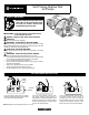

APPLICATION
Theshallowwelljetpumpisidealforthesupplyoffreshwaterto
ruralhomes,farmsandcabins.Thispumpissuitableforinstallations
where the vertical distance from the pump to the water level does not
exceed*25ft.(7.6m),includingdrawdown.Inoff-setinstallations,
friction losses in the suction pipe must be taken into consideration .
(RefertoTable2,FrictionLoss.)
*Lessathighaltitudes.
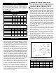
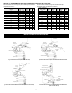
PERFORMANCE
U.S. Gallons per minute, at 30 PSI at Total Suction Lift
in feet below.
PUMP HP 5' 10' 15' 20' 25'
1/3 9.7 8.3 7.0 5.6 4.1
1/2 12.3 11.0 9.6 7.8 5.5
3/4 15.8 13.7 11.3 9.3 7.0
1 23.2 20.1 17.4 14.2 10.4
1/2 HP High Press. 8.6 7.6 6.3 5.1 3.6
Litres per minute, at 30 PSI at
Total Suction Lift in metres below.
PUMP HP 1.5m 3.0m 4.5m 6.0m 7.5m
1/3 36.7 31.4 26.5 21.2 15.5
1/2 46.6 41.7 36.4 29.5 20.8
3/4 59.8 51.9 42.8 35.2 26.5
1 87.8 76.0 65.8 53.7 39.4
1/2 HP High Press. 32.6 28.6 23.9 19.3 13.6
INSTALLATION
a)PumpLocation: Thepump shouldbe installedin aclean, dry
and ventilated location which provides adequate room for ser-
vicingandprotectionfromfreezingtemperatures.Itshouldbe
bolted to a good foundation, preferably concrete and provided
withadequatedrainage.Locatingthepumpascloseaspossible
to the water source reduces the friction in the suction pipe and
will give maximum capacities.
b)SuctionPipe:Itisrecommendedthatonlynew,clean1-1/4inch
pipeorhosebeused.Ifthepumpisinstalledanyappreciabledis-
tance away from the source of water, the suction pipe should be
increasedto1-1/2inches.Horizontallengthsofpipemustgradu-
ally slope upwards from the source of water to the pump to avoid
airpocketsintheline.Threadcompoundshouldbeusedonall
pipejointsandconnectionsshouldbethoroughlytightened.Afoot
valve must be installed and its operation should be checked since
aleakwillpreventproperoperationofthesystem.Makesurethe
footvalveislocatedsothatitwillbesubmergedatalltimes.Ifa
sandpoint or driven well is used, install a check valve next to the
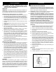
pumpsuctioninsteadofthe footvalve (Fig.2b).Allinstallations
must have a foot valve or a check valve in the suction pipe.
c) PumptoTankFittings:Thedischargepipefromthepumptothe
tank should be as short and direct as possible and should be the
samesizeasthatofthepumpdischargetapping.Acheckvalve
should never be installed between the pump and the tank.
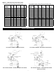
d) ServiceLine: The servicelineshould be connectedas shown
inFig.2a,b,cord.Thesizeoftheservicelinerequiredisgov-
erned entirely by the amount of water needed and the length of
thepipe.Thepipeselectedshouldbelargeenoughsothatthe
frictionloss(determinedfromTable2,FrictionLossChart)will
never exceed 20 ft. (6m) head.
WARNING - ELECTRICAL PRECAUTIONS
All wiring, electrical connections, and system grounding must
comply with the National Electrical Code (NEC) and with any
local codes and ordinances. Employ a licensed electrician.
WARNING - RISK OF ELECTRICAL SHOCK
e) Wiring:Anelectricianshouldbeemployedtodothewiringand
connecttheelectricalservicetothepump.Thepressureswitch
is wired to the motor at the factory and the voltage for which
the motor is wired is indicated by a sticker where applicable.
Makesurethemotoriswiredforthesamevoltageasthepower
supply. Refer to the motor nameplate or inside terminal cover
for voltage changing instructions. The power lines should be
connected to the pressure switch terminals marked "line" (see
Fig.1).Itisrecommendedthataseparatecircuitbeledfromthe
distribution panel to the pump unit. A ground fault interrupter
(GFI)protectedcircuitshouldbeusedforallelectricaldevices
operatingnearwater.Installaproperfuseddisconnectswitchin
thelineandmakecertainthewiringisadequatelysizedandwell
insulated. Undersized wire between the motor and the power
source will adversely limit the starting and load carrying abilities
ofthemotor.Minimumwiresizesformotorbranchcircuitsare
recommended(seeTable1).Foraddedsafety,thepumpand
motor should be grounded to the well casing or the ground in
the distribution panel.
f) PressureGauge:Ifapressuregaugeissuppliedwiththepump
or if you wish to install a pressure gauge, it should be installed
intothe1/4"NPTholeonthefrontofthecasingdirectlybeside
the discharge opening.
g)AirVolumeControl:Ifnoperma-pressuretankisusedinapres-
sure system, an air volume control must be used to maintain an
air cushion in the pressure tank. Refer to pressure tank owner's
manual for instructions.
h) PressureReliefValve:Ahighpressuresafetyreliefvalveisrec-
ommended to be installed at some point in the water system.
Ensure its location is near the discharge of the pump, in an area
with adequate drainage. Be sure to direct the valve such that any
water flow could not spray toward any electrical devices.
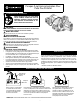
Fig. 1 Electrical Connections
Ground
L1
L2
Pressure
Switch
Motor (Load)
Power
Supply
(Line)
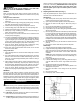
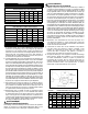
TABLE 1 – MAXIMUM WIRE LENGTH (FT.)
Motor Wire Gauge (AWG)
HP Volts 0-25 ft. 50 ft. 100 ft. 150 ft. 200 ft.
1/3 115 14 14 14 12 10
1/2 115 14 14 12 10 8
3/4 115 14 14 10 8 8
1 115 14 12 10 8 6
Based on approx. 3% voltage drop.
2