
User Manual

43
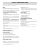
SERIAL RLC PROTOCOL COMMUNICATIONS
RLC Communications requires the Serial Communications Type Parameter
(tYPE) be set to “rLC”.
SENDING SERIAL COMMANDS AND DATA TO THE METER
When sending commands to the meter, a string containing at least one
command character must be constructed. A command string consists of a
command character, a value identifier, numerical data (if writing data to the
meter) followed by a command terminator character * or $.
Command Chart
COMMAND DESCRIPTION NOTES
N Node (Meter)
Address
Specifier
Address a specific meter. Must be followed by a
two digit node address. Not required when
address = 00.
T Transmit Value
(read)
Read a register from the meter. Must be followed
by register ID character
V Value Change
(write)
Write to register of the meter. Must be followed by
register ID character and numeric data.
R Reset Reset a register or output. Must be followed by
register ID character.
P Block Print
Request
Initiates a block print output. Registers are defined
in programming.
*, $ Terminator Signifies end of transmission
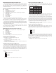
Command String Construction
The command string must be constructed in a specific sequence. The meter
does not respond with an error message to invalid commands. The following
procedure details construction of a command string:
1. The first characters consist of the Node Address Specifier (N) followed by a
2 character address number. The address number of the meter is programmable.
If the node address is 0, this command and the node address itself may be
omitted. This is the only command that may be used in conjunction with other
commands.
2. After the optional address specifier, the next character is the command
character.
3. The next character is the Register ID. This identifies the register that the
command affects. The P command does not require a Register ID character.
It prints according to the selections made in print options.
4. If constructing a value change command (writing data), the numeric data is
sent next.
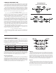
5. All command strings must be terminated with the string termination
characters *, or $. The meter does not begin processing the command string
until this character is received. See Timing Diagram figure for differences
between terminating characters.
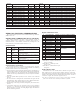
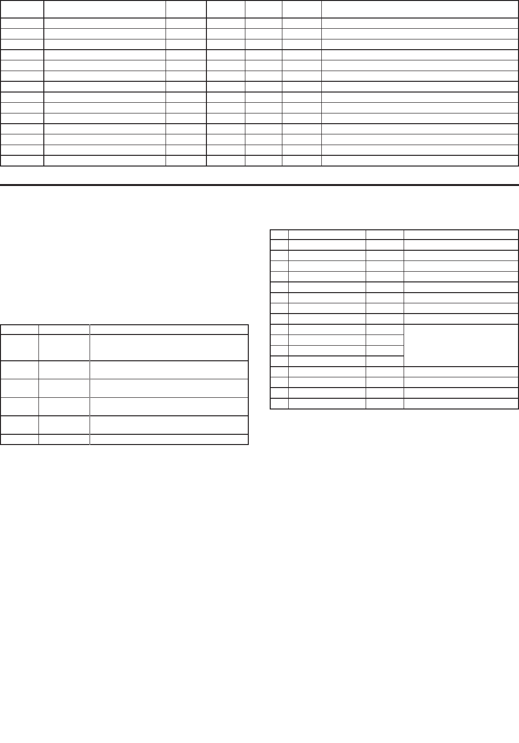
Register Identification Chart
ID VALUE DESCRIPTION MNEMONIC APPLICABLE COMMANDS/COMMENTS
A Signal Input INP T, P
B Active Setpoint SET T, V, P
C Setpoint Ramp Rate RMP T, V, P
D Output Power PWR T, V, P (V only in manual mode)
E Proportional Band PBD T, V, P
F Integral Time INT T, V, P
G Derivative Time DER T, V, P
H Alarm Status (1-4) ALR T, R, P
I Alarm Value 1 AL1 T, V, R, P (Reset command resets
Alarm Outputs)
J Alarm Value 2 AL2
K Alarm Value 3 AL3
L Alarm Value 4 AL4
M Control Parameters CTL T, V, P
O Auto/Manual Register MMR T, V
Q Analog Output Register AOR T, V
S Digital Output Register DOR T, V
Command String Examples:
1. Node address = 17, Write 350 to Alarm 1.
String: N17VI350$
2. Node address = 5, Read Input value.
String: N5TA*
3. Node address = 0, Reset Alarm 4 output.
String: RL*
Sending Numeric Data
Numeric data sent to the controller must be limited to 4 digits (-1999 to
9999). Leading zeros are ignored. Negative numbers must have a minus sign.
The controller ignores any decimal point and conforms the number to the scaled
resolution. (For example: the meter’s scaled decimal point position = 0.0 and 25
is written to a register. The value of the register is now 2.5.
Note: Since the controller does not issue a reply to value change commands,
follow with a transmit value command for readback verification.
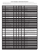
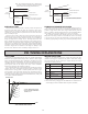
REGISTER
ADDRESS
REGISTER NAME LOW LIMIT HIGH LIMIT
FACTORY
SETTING
ACCESS COMMENTS
40051 Active Alarm 3 Band/Dev. Value -1999 9999 0 Read/Write Active List (A or B). Only for Band or Deviation Alarm Action.
40052 Active Alarm 4 Band/Dev. Value -1999 9999 0 Read/Write Active List (A or B). Only for Band or Deviation Alarm Action.
40053 Active Alarm 5 Band/Dev. Value -1999 9999 0 Read/Write Active List (A or B). Only for Band or Deviation Alarm Action.
40054 Active Alarm 6 Band/Dev. Value -1999 9999 0 Read/Write Active List (A or B). Only for Band or Deviation Alarm Action.
40055 Active Alarm 7 Band/Dev. Value -1999 9999 0 Read/Write Active List (A or B). Only for Band or Deviation Alarm Action.
40056 Active Alarm 8 Band/Dev. Value -1999 9999 0 Read/Write Active List (A or B). Only for Band or Deviation Alarm Action.
40057 Active Alarm 9 Band/Dev. Value -1999 9999 0 Read/Write Active List (A or B). Only for Band or Deviation Alarm Action.
40058 Active Alarm 10 Band/Dev. Value -1999 9999 0 Read/Write Active List (A or B). Only for Band or Deviation Alarm Action.
40059 Active Alarm 11 Band/Dev. Value -1999 9999 0 Read/Write Active List (A or B). Only for Band or Deviation Alarm Action.
40060 Active Alarm 12 Band/Dev. Value -1999 9999 0 Read/Write Active List (A or B). Only for Band or Deviation Alarm Action.
40061 Active Alarm 13 Band/Dev. Value -1999 9999 0 Read/Write Active List (A or B). Only for Band or Deviation Alarm Action.
40062 Active Alarm 14 Band/Dev. Value -1999 9999 0 Read/Write Active List (A or B). Only for Band or Deviation Alarm Action.
40063 Active Alarm 15 Band/Dev. Value -1999 9999 0 Read/Write Active List (A or B). Only for Band or Deviation Alarm Action.
40064 Active Alarm 16 Band/Dev. Value -1999 9999 0 Read/Write Active List (A or B). Only for Band or Deviation Alarm Action.