
Manual


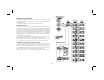


FACTORY SETTINGS
MASTER MODE: FOLLOWER MODE:
USER SETPOINTS: USER SETPOINTS:
S1 500 S1
1.0000
S2 1000 S2 0.5000
R1 100 R1
0.1000
R2 200 R2
0.2000
DISPLAY 1 DISPLAY 1
LINE 1 SPD-MNE LINE 1 SPD-MNE
LINE 2 SPD-VAL LINE 2 SPD-VAL
DISPLAY 2 DISPLAY 2
LINE 1 OP STAT LINE 1 OP-STAT
LINE 2 SPD- VAL LINE 2 SPD-VAL
DISPLAY 3 DISPLAY 3
LINE 1 AL STAT LINE 1 LDHZ-VAL
LINE 2 SPD -VAL LINE 2 FBHZ-VAL
DISPLAY 4 DISPLAY 4
LINE 1 TRIM-VAL LINE 1 TRIM-VAL
LINE 2 SPD -VAL LINE 2 SPD-VAL
SCALING:
PPR LD 60
MAX RPM LD 1750
-27-
USER SETTINGS
This Menu should only be entered if the operator wants to reset ALL
parameters in either Master or Follower mode to the factory settings. If the
MDC is in Master Mode when the word “FACTORY” is flashing in the
display and the ENT key is pressed, all parameters for that mode are reset to
the factory settings upon exiting the Programming Module. The same is true
for Follower Mode. Parameters common to both Master and Follower modes
are reset regardless of the operating mode. The operator can exit the factory
settings option WITHOUT resetting all parameters by pressing the <ESC
key. The following are the settings when shipped from the factory, along with
a chart for user settings:
Caution: If factory settings are selected, all programming by the user for that
operating mode will be reset.
FACTORY SETTINGS COMMON TO MASTER AND FOLLOWER MODES:
USER SETPOINTS: OPTIONS:
JOG SPD 200 Operator Access:
JOG RAMP 50 S1 YES
AL-1 1200 S2 YES
AL-2 100 R1 YES
GAIN 99 R2 YES
JOG SPD YES
SCALING: JOG RAMP YES
PPR FB 60 AL-1 YES
MAX RPM FB 1750 AL-2 YES
DSP DP 0 GAIN YES
DSP UNIT 1750 SPT SCROLL YES
USER INPUTS: No Feedback Detection: YES
User Input 1 NO MODE
User Input 2 NO MODE
User Input 3 NO MODE
User Input 4 NO MODE
User Key F1 RUN
User Key F2 R-STOP
ALARM OUTPUTS:
ALARM 1:
Alarm Type HIGH ALM
Phase + PHASE
Latched/Boundary BOUNDARY
Update NORM UPD
ALARM 2:
Alarm Type LOW ALM
Phase + PHASE
Latched/Boundary BOUNDARY
Update NORM UPD
Stop Mode Status STP DSBL
DISPLAY:
Scroll Speed NONE