
User guide
CAUTION: The MPAX main circuit board and the option cards
contain static sensitive components. Before handling the module
or the cards, discharge static charges from your body by
touching a grounded bare metal object. Handle the module by
the rear plastic cover only, and the option cards by the board
edges. Dirt, oil or other contaminants that contact the circuit
boards or components can adversely affect circuit operation.
WARNING: Exposed line voltage exists on the MPAX main circuit
board and the option cards. DO NOT apply power to the
module OR load circuits until the module is properly installed
in the LPAX case.
NOTE: All module and option card labels must be installed as
shown for safety purposes.
3
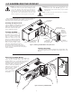
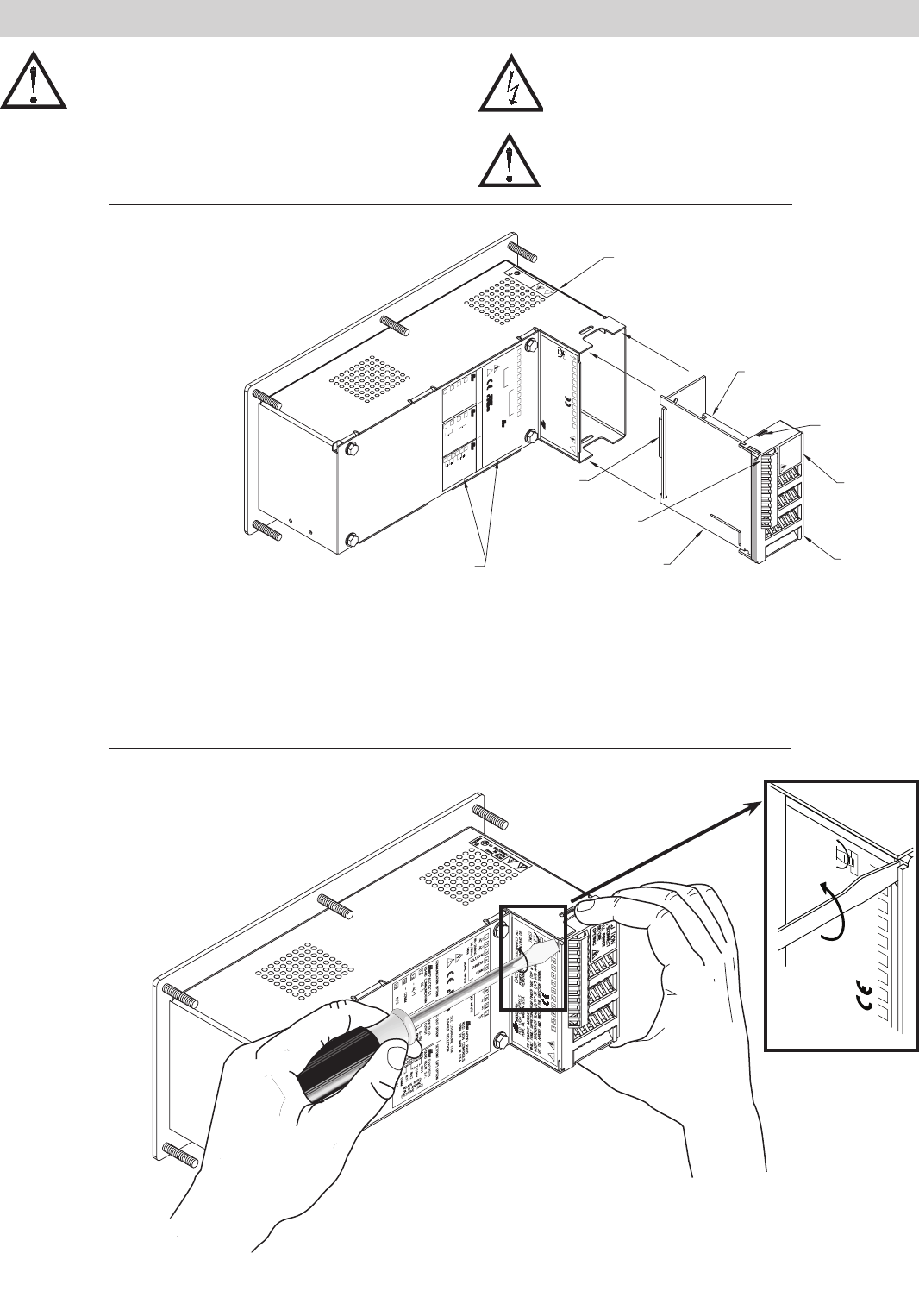
Removing The MPAX Module
To remove the MPAX Module from the LPAX Display, first
remove all power and load circuits. Then insert a flat
screwdriver blade (
3
/
16
" or
1
/
4
") into the narrow slot between
the LPAX rear cover plate and the module’s plastic cover
as illustrated in Figure 2. Twist the screwdriver in
the direction shown to disengage the internal
connectors while firmly squeezing and
pulling back on the rear finger tabs
(top and bottom). Carefully
slide the module out of the
LPAX case, keeping it
properly aligned with the
case opening.
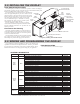
1.0 ASSEMBLING THE DISPLAY
Prior to installing the LPAX Display, it is recommended that the MPAX and
any option cards be assembled first. This will allow you the opportunity to
insure all the boards are fitted properly into their connectors.
Installing the Option Cards
If your application requires option cards, they
should be installed into the MPAX before it is
installed into the LPAX Display. Refer to
the literature enclosed with the option
cards for installation instruction.
Installing the MPAX
To install the MPAX Module, align
the module with the opening in the
LPAX case, as illustrated. The module
must be oriented as shown, with
terminal #1 toward the top of the
LPAX case. Carefully slide the module
into the LPAX case. The LPAX and
MPAX connectors will begin to engage
about ¼" from the bottom. At this
point, apply a small amount of pressure to
the rear of the MPAX module to fully engage
the connection. Be sure the module fully snaps into
the slots at the rear of the LPAX case. The display is
ready for installation.
Installing the Labels
Each option card and the MPAX are shipped with a connection label. These
labels must be applied to the rear of the LPAX in the positions shown in the
drawing.
CAUTION:
123
45
6
7
8
9
10
11
DISCONNECT ALL
POWER BEFORE INSTALLING OR
REMOVING MODULE
SLOT
TWIST
!
WHILE FIRMLY DEPRESSING REAR FINGER TABS (TOP & BOTTOM),
INSERT SCREWDRIVER BLADE (3/16" OR 1/4") INTO NARROW SLOT
(AT THE ARROW) AND TWIST IN THE DIRECTION SHOWN.
TO REMOVE MODULE:
MODEL LPAX
RED LION CONTROLS
YORK, PA. MADE IN U.S.A.
PAXCDC10
RS485 COMMUNICATION
12
13
14
15
- B(-)
- A(+)
- COMM
- N/C
1 2 3 4 5 6
7
8 9 10 11
~ ~
AC AC
85-250VAC
50/60Hz
14VA
COMMUNICATION OPTION ANALOG OUT OPTION
SETPOINT (SP) OPTION
MODEL PAXD
RED LION CONTROLS
YORK, PA. MADE IN U.S.A.
SEE LITERATURE FOR
JUMPER SELECTION
SIGNAL INPUTS
USER INPUTS
VOLT/OHM
CURRENT
+EXCITATION
COMM
1
2
3
N/C
COMM
!
R
-19
17
+18
-
+16
ANALOG OUTPUT
PAXCDL10
RLY3
25
21
RLY2
22
COMM
RLY1
20
QUAD RELAY S.P.
PAXCDS20
0-10V
ANALOG
OUTPUT
OUTPUT
ANALOG
0-20mA
24
23
COMM
RLY4
RELAYS RATED
3A @ 250VAC
(RESISTIVE LOAD)
MODULE
CONNECTOR
MODULE
REAR COVER
CAUTION
LABEL
MODULE
RETENTION
LATCH (TOP
AND BOTTOM)
OPTION CARD(S)
INSTALLED ON THIS SIDE
MPAX MAIN
CIRCUIT BOARD
(BOTTOM SIDE)
TERMINAL #1
MODULE AND
OPTION CARD(S) LABELS
(APPLY TO REAR COVER PLATE)
CAUTION
DISCONNECT
ALL POWER
BEFORE
OPENING
LPAX DISPLAY
REAR VIEW
METAL PANEL
MUST BE
CONNECTED TO
!
E
MA2204X
Figure 1, Installing an MPAX Module and Option Cards
8
SLOT
7 654 32
TWIST
Figure 2, Removing an MPAX Module