
User Manual


5
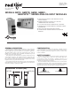
WIRING
WIRING CONNECTIONS
All conductors should meet voltage and current ratings
for each terminal. Also, cabling should conform to
appropriate standards of good installation, local codes and
regulations and be suitably rated for the temperatures of
the environment to which it is being installed. When
wiring the module, use the numbers on the label to identify
the position number with the proper function. Strip the
wire, leaving approximately 1/4" (6 mm) of bare wire
exposed. Insert the wire into the terminal, and tighten.
Terminals 13 to 18
Terminals 7 to 12
Terminals 1 to 6
GMTC
INPUT CONNECTIONS
321
-TC
+TC
5
46
1
15
9
78
13
14
1110 12
N/C
N/C
1716 18
-TC
+TC
2
-TC
+TC
3
-TC
-TC
+TC
4
-TC
+TC
+TC
56
-TC
-TC
+TC
7
+TC
8
+
5
46
123
+SIG
COMM.
1
+EXC
87 109 1211
1413 1615 1817
COMM.
+SIG
2
+EXC
COMM.
+SIG
3
COMM.
+EXC
+EXC
+SIG
4
COMM.
+SIG
5
COMM.
+EXC
+EXC
+SIG
6
SENSE
SENSE
EXC./
JUMPER
312
COMM.
0-20mA
1
54 6
9
15
78
13 14
1110 12
N/C
N/C
1716 18
2
0-20mA
COMM.
3
COMM.
0-20mA
COMM.
0-20mA
COMM.
4
0-20mA
0-20mA
COMM.
56
COMM.
0-20mA
COMM.
7
0-20mA
8
LOAD
POWER
+
+
_
_
COMM.
321
+/-10V
COMM.
1
645
+/-10V
+/-10V
COMM.
23
+/-10V
COMM.
+/-10V
COMM.
N/C
N/C
COMM.
15
9
COMM.
+/-10V
7 8
4
13 14
COMM.
+/-10V
+/-10V
1110 12
56
1716 18
78
GMRTD
GMINI
GMINV