
Owner's manual


5
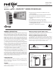
WIRING
WIRING CONNECTIONS
All conductors should meet voltage
and current ratings for each terminal.
Also, cabling should conform to
appropriate standards of good installation,
local codes and regulations and be
suitably rated for the temperatures of the
environment to which it is being installed.
When wiring the module, use the numbers
on the label to identify the position
number with the proper function. Strip
the wire, leaving approximately 1/4" (6
mm) of bare wire exposed. Insert the wire
into the terminal, and tighten.
Terminals 13 to 18
Terminals 7 to 12
Terminals 1 to 6
Terminals 19 to 24
(GMP2 Only)
TC/RTD+
INPUT COM.
4-20 mA
0-10 V
N/C
RTD +EXE
1 32 54 6
SENSE
SENSE
EXC./
JUMPER
654321
0-10 V
4-20 mA
N/C
TC/RTD+
INPUT COM.
RTD +EXE
+
654321
0-10 V
4-20 mA
N/C
TC/RTD+
INPUT COM.
RTD +EXE
LOAD
POWER
+
+
_
_
654321
0-10 V
4-20 mA
N/C
TC/RTD+
INPUT COM.
RTD +EXE
VDC-
VDC+
121110987
HCM (OPT)
HCM (OPT)
OP2 COM
OP1 COM
OP1 +
OP2 +
Heater Circuit
AC
RTD
Heater Current Monitor
Voltage
GMP1 INPUT CONNECTIONS
Current
Thermocouple and Millivolt
TC/RTD+
INPUT COM.
4-20 mA
0-10 V
N/C
RTD +EXE
1 32 54 6
SENSE
SENSE
EXC./
JUMPER
INPUT 1
TC/RTD+
INPUT COM.
4-20 mA
0-10 V
N/C
RTD +EXE
7 98 1110 12
INPUT 2
654321
0-10 V
4-20 mA
N/C
TC/RTD+
INPUT COM.
RTD +EXE
0-10 V
4-20 mA
N/C
TC/RTD+
INPUT COM.
RTD +EXE
+
121110987
INPUT 1
INPUT 2
654321
0-10 V
4-20 mA
N/C
TC/RTD+
INPUT COM.
RTD +EXE
0-10 V
4-20 mA
N/C
TC/RTD+
INPUT COM.
RTD +EXE
121110987
INPUT 1
INPUT 2
LOAD
POWER
+
+
_
_
654321
0-10 V
4-20 mA
N/C
TC/RTD+
INPUT COM.
RTD +EXE
121110987
0-10 V
4-20 mA
N/C
TC/RTD+
INPUT COM.
RTD +EXE
VDC-
VDC+
INPUT 1
INPUT 2
242322212019
HCM
HCM
HCM
OP4 COM
OP4 +
HCM
Heater Circuit
AC
2
1
SAME AS
HCM 1
{
RTD
Heater Current Monitor
Voltage
GMP2 INPUT CONNECTIONS
Current
Thermocouple and Millivolt