
Owner manual


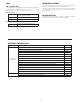


WIRING
WIRING CONNECTIONS
All conductors should meet voltage and current
ratings for each terminal. Also, cabling should conform
to appropriate standards of good installation, local
codes and regulations and be suitably rated for the
temperatures of the environment to which it is being
installed. When wiring the module, use the numbers
on the label to identify the position number with the
proper function. Strip the wire, leaving approximately
1/4" (6 mm) of bare wire exposed. Insert the wire into
the terminal, and tighten.
4
OUTPUT CONNECTIONS
IN 8
IN 7
IN 6
IN 3
IN 4
IN 5
13 14 15 16 17 18
+
10789
-
11 12
IN 2
1278 109 11
COM IN
IN 1
IN 3
IN 4
IN 5
IN 6
IN 7
1413 1615 17
IN 8
18
IN 2
COM IN
IN 1
INPUT CONNECTIONS
COM1, 2
OUT 2
OUT 1
1 23
COM3, 4
OUT 3
OUT 4
4 5 6
7 8910 11 12
OUT 6
COM5, 6
OUT 5
+
-
Load
+
-
2
OUT 1
COM1, 2
1
OUT 3
COM3, 4
OUT 2
3 45
8
7109 11
OUT 5
COM5, 6
OUT 6
OUT 4
6
12
Load
Power
Solid State NFET VersionRelay VersionSourcing InputSinking Input
Terminals 13 to 18
Terminals 7 to 12
Terminals 1 to 6
HARDWARE INSTALLATION
Modules must be installed beginning with slot 1 (left-most slot), with no
empty slots between the modules, and the order must match the modules order
in Crimson. Torque screws to 6.0 pound-force inch (96 ounce-force inch)
REMOVE RUBBER
MODULE PLUG
WARNING: Disconnect all power
to the unit before installing or
removing modules.