Configuring and Managing a Red Hat Cluster Red Hat Cluster for Red Hat Enterprise Linux 5
Configuring and Managing a Red Hat Cluster: Red Hat Cluster for Red Hat Enterprise Linux 5 Copyright © 2007 Red Hat, Inc. Configuring and Managing a Red Hat Cluster describes the configuration and management of Red Hat cluster systems for Red Hat Enterprise Linux 5. It does not include information about Red Hat Linux Virtual Servers (LVS). Information about installing and configuring LVS is in a separate document.
Table of Contents Introduction ............................................................................................................... vi 1. Document Conventions ................................................................................. vii 2. Feedback .................................................................................................... viii 1. Red Hat Cluster Configuration and Management Overview ....................................... 1 1. Configuration Basics ...............
Configuring and Managing a Red Hat Cluster 5.3. Deleting a Member from a Cluster .......................................................45 6. Configuring a Failover Domain .......................................................................46 6.1. Adding a Failover Domain ...................................................................47 6.2. Removing a Failover Domain ..............................................................50 6.3. Removing a Member from a Failover Domain .......................
Introduction This document provides information about installing, configuring and managing Red Hat Cluster components. Red Hat Cluster components are part of Red Hat Cluster Suite and allow you to connect a group of computers (called nodes or members) to work together as a cluster. This document does not include information about installing, configuring, and managing Linux Virtual Server (LVS) software. Information about that is in a separate document.
1. Document Conventions • Linux Virtual Server Administration — Provides information on configuring high-performance systems and services with the Linux Virtual Server (LVS). • Red Hat Cluster Suite Release Notes — Provides information about the current release of Red Hat Cluster Suite. Red Hat Cluster Suite documentation and other Red Hat documents are available in HTML, PDF, and RPM versions on the Red Hat Enterprise Linux Documentation CD and online at http://www.redhat.com/docs/. 1.
2. Feedback Tip A tip is typically an alternative way of performing a task. Important Important information is necessary, but possibly unexpected, such as a configuration change that will not persist after a reboot. Caution A caution indicates an act that would violate your support agreement, such as recompiling the kernel. Warning A warning indicates potential data loss, as may happen when tuning hardware for maximum performance. 2.
Chapter 1. Red Hat Cluster Configuration and Management Overview Red Hat Cluster allows you to connect a group of computers (called nodes or members) to work together as a cluster. You can use Red Hat Cluster to suit your clustering needs (for example, setting up a cluster for sharing files on a GFS file system or setting up service failover). 1. Configuration Basics To set up a cluster, you must connect the nodes to certain cluster hardware and configure the nodes into the cluster environment.
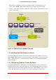
1.2. Installing Red Hat Cluster software Other options are available for storage according to the type of storage interface; for example, iSCSI or GNBD. A Fibre Channel switch can be configured to perform fencing. • Storage — Some type of storage is required for a cluster. The type required depends on the purpose of the cluster. Figure 1.1. Red Hat Cluster Hardware Overview 1.2. Installing Red Hat Cluster software To install Red Hat Cluster software, you must have entitlements for the software.
1.3. Configuring Red Hat Cluster Software grouped into a failover domain for a cluster service. The services comprise resources such as NFS exports, IP addresses, and shared GFS partitions. Figure 1.2. Cluster Configuration Structure The following cluster configuration tools are available with Red Hat Cluster: • Conga — This is a comprehensive user interface for installing, configuring, and managing Red Hat clusters, computers, and storage attached to clusters and computers.
2. Conga In addition, information about using Conga and system-config-cluster is provided in subsequent chapters of this document. Information about the command line tools is available in the man pages for the tools. 2. Conga Conga is an integrated set of software components that provides centralized configuration and management of Red Hat clusters and storage.
2. Conga ine which users are allowed to access clusters and computers registered in the luci database. It is possible to import users as a batch operation in a new luci server, just as it is possible to import clusters and computers. When a computer is added to a luci server to be administered, authentication is done once. No authentication is necessary from then on (unless the certificate used is revoked by a CA).
2. Conga Figure 1.4.
3. system-config-cluster Cluster Administration GUI Figure 1.5. luci storage Tab 3. system-config-cluster Cluster Administration GUI This section provides an overview of the cluster administration graphical user interface (GUI) available with Red Hat Cluster Suite — system-config-cluster. The GUI is for use with the cluster infrastructure and the high-availability service management components. The GUI consists of two major functions: the Cluster Configuration Tool and the Cluster Status Tool.
3.1. Cluster Configuration Tool Figure 1.6. Cluster Configuration Tool The Cluster Configuration Tool represents cluster configuration components in the configuration file (/etc/cluster/cluster.conf) with a hierarchical graphical display in the left panel. A triangle icon to the left of a component name indicates that the component has one or more subordinate components assigned to it. Clicking the triangle icon expands and collapses the portion of the tree below a component.
3.2. Cluster Status Tool elements under Fence Devices. Using configuration buttons at the bottom of the right frame (below Properties), you can add fence devices, delete fence devices, and edit fence-device properties. Fence devices must be defined before you can configure fencing (with the Manage Fencing For This Node button) for each node. • Managed Resources — Displays failover domains, resources, and services.
4. Command Line Administration Tools Figure 1.7. Cluster Status Tool The nodes and services displayed in the Cluster Status Tool are determined by the cluster configuration file (/etc/cluster/cluster.conf). You can use the Cluster Status Tool to enable, disable, restart, or relocate a high-availability service. 4.
5. Configuration Considerations Command Line Tool Used With Purpose — Cluster InfraCluster Configur- structure ation System Tool ccs_tool — Cluster Management Tool Cluster Infrastructure cman_tool Cluster Infrastructure fence_tool clustat — Cluster Status Utility High-availability Service Management Components The clustat command displays the status of the cluster. It shows membership information, quorum view, and the state of all configured user services.
5. Configuration Considerations Certain low-cost alternatives, such as host RAID controllers, software RAID without cluster support, and multi-initiator parallel SCSI configurations are not compatible or appropriate for use as shared cluster storage. Data integrity assurance To ensure data integrity, only one node can run a cluster service and access cluster-service data at a time.
Chapter 2. Configuring Red Hat Cluster With Conga This chapter describes how to configure Red Hat Cluster software using Conga, and consists of the following sections: • Section 1, “Configuration Tasks” • Section 2, “Starting luci and ricci”.
2. Starting luci and ricci To administer Red Hat Clusters with Conga, install and run luci and ricci as follows: 1. At each node to be administered by Conga, install the ricci agent. For example: # yum install ricci 2. At each node to be administered by Conga, start ricci. For example: # service ricci start Starting ricci: 3. [ OK ] Select a computer to host luci and install the luci software on that computer.
3. Creating A Cluster (or the equivalent). The URL syntax for the luci server is https://luci_server_hostname:8084. The first time you access luci, two SSL certificate dialog boxes are displayed. Upon acknowledging the dialog boxes, your Web browser displays the luci login page. 3. Creating A Cluster Creating a cluster with luciconsists of selecting cluster nodes, entering their passwords, and submitting the request to create a cluster.
4. Global Cluster Properties • The Cluster Name text box displays the cluster name; it does not accept a cluster name change. You cannot change the cluster name. The only way to change the name of a Red Hat cluster is to create a new cluster configuration with the new name. • The Configuration Version value is set to 1 by default and is automatically incremented each time you modify your cluster configuration.
5. Configuring Fence Devices Note For more information about setting Quorum Partition parameters, refer to the qdisk(8) man page. 5. Configuring Fence Devices Configuring fence devices consists of creating, modifying, and deleting fence devices. Creating a fence device consists of selecting a fence device type and entering parameters for that fence device (for example, name, IP address, login, and password).
5.1. Creating a Shared Fence Device • Dell DRAC • HP iLO • IBM RSA II • IPMI LAN • RPS10 Serial Switch This section provides procedures for the following tasks: • Creating shared fence devices — Refer to Section 5.1, “Creating a Shared Fence Device”. The procedures apply only to creating shared fence devices. You can create non-shared (and shared) fence devices while configuring nodes (refer to Section 6, “Configuring Cluster Members”).
5.2. Modifying or Deleting a Fence Device Figure 2.1. Fence Device Configuration 3. At the Add a Sharable Fence Device page, click the drop-down box under Fencing Type and select the type of fence device to configure. 4. Specify the information in the Fencing Type dialog box according to the type of fence device. Refer to Appendix B, Fence Device Parameters for more information about fence device parameters. 5. Click Add this shared fence device. 6.
6. Configuring Cluster Members 1. At the detailed menu for the cluster (below the clusters menu), click Shared Fence Devices. Clicking Shared Fence Devices causes the display of the fence devices for a cluster and causes the display of menu items for fence device configuration: Add a Fence Device and Configure a Fence Device. 2. Click Configure a Fence Device. Clicking Configure a Fence Device causes the display of a list of fence devices under Configure a Fence Device. 3.
6.2. Adding a Member to a Running Cluster 1. At the detailed menu for the cluster (below the clusters menu), click Nodes. Clicking Nodes causes the display of an Add a Node element and a Configure element with a list of the nodes already configured in the cluster. 2. Click a link for a node at either the list in the center of the page or in the list in the detailed menu under the clusters menu. Clicking a link for a node causes a page to be displayed for that link showing how that node is configured.
6.3. Deleting a Member from a Cluster d. Joining the added node to cluster. A progress page shows the progress of those actions for each added node. 5. When the process of adding a node is complete, a page is displayed providing a configuration interface for the cluster. 6. At the detailed menu for the cluster (below the clusters menu), click Nodes.
7. Configuring a Failover Domain 2. Disable or relocate each service that is running on the node to be deleted: Note Repeat this step for each service that needs to be disabled or started on another node. 3. a. Under Services on this Node, click the link for a service. Clicking that link cause a configuration page for that service to be displayed. b. On that page, at the Choose a taskdrop-down box, choose to either disable the service are start it on another node and click Go. c.
7.1. Adding a Failover Domain Note Changing a failover domain configuration has no effect on currently running services. Note Failover domains are not required for operation. By default, failover domains are unrestricted and unordered. In a cluster with several members, using a restricted failover domain can minimize the work to set up the cluster to run a cluster service (such as httpd), which requires you to set up the configuration identically on all members that run the cluster service).
7.2. Modifying a Failover Domain 3. At the Add a Failover Domain page, specify a failover domain name at the Failover Domain Name text box. Note The name should be descriptive enough to distinguish its purpose relative to other names used in your cluster. 4. To enable setting failover priority of the members in the failover domain, click the Prioritized checkbox. With Prioritized checked, you can set the priority value, Priority, for each node selected as members of the failover domain. 5.
8. Adding Cluster Resources 4. Modifying failover name — To change the failover domain name, modify the text at the Failover Domain Name text box. Note The name should be descriptive enough to distinguish its purpose relative to other names used in your cluster. 5. Failover priority — To enable or disable prioritized failover in this failover domain, click the Prioritized checkbox.
8. Adding Cluster Resources select the type of resource to configure. The resource options are described as follows: GFS Name — Create a name for the file system resource. Mount Point — Choose the path to which the file system resource is mounted. Device — Specify the device file associated with the file system resource. Options — Mount options. File System ID — When creating a new file system resource, you can leave this field blank.
8. Adding Cluster Resources Monitor Link checkbox — Check the box to enable or disable link status monitoring of the IP address resource NFS Mount Name — Create a symbolic name for the NFS mount. Mount Point — Choose the path to which the file system resource is mounted. Host — Specify the NFS server name. Export Path — NFS export on the server. NFS version — Specify NFS protocol: • NFS3 — Specifies using NFSv3 protocol. The default setting is NFS. • NFS4 — Specifies using NFSv4 protocol.
9. Adding a Cluster Service to the Cluster directly to service, not to a resource within a service. 4. Click Submit. Clicking Submit causes a progress page to be displayed followed by the display of Resources forcluster name page. That page displays the added resource (and other resources). 9. Adding a Cluster Service to the Cluster To add a cluster service to the cluster, follow the steps in this section.
10. Configuring Cluster Storage Note If you are adding a Samba-service resource, connect a Samba-service resource directly to the service, not to a resource within a service. 6. If you want to add resources to that resource, click Add a child. Clicking Add a child causes the display of additional options to local and global resources. You can continue adding children resources to the resource to suit your requirements. To view children resources, click the triangle icon to the left of Show Children. 7.
10. Configuring Cluster Storage forms throughout the storage user interface. This general choice allows you to avoid difficult decimal representations of storage size (for example, if you know that most of your storage is measured in gigabytes, terabytes, or other more familiar representations). Additionally, the Welcome to Storage Configuration Interface page lists systems that you are authorized to access, but currently are unable to administer because of a problem.
Chapter 3. Managing Red Hat Cluster With Conga This chapter describes various administrative tasks for managing a Red Hat Cluster and consists of the following sections: • Section 1, “Starting, Stopping, and Deleting Clusters” • Section 2, “Managing Cluster Nodes” • Section 3, “Managing High-Availability Services” • Section 4, “Diagnosing and Correcting Problems in a Cluster” 1.
2. Managing Cluster Nodes node. You can select this action for any state the cluster is in. Deleting a cluster frees each node in the cluster for use in another cluster. 2. Select one of the functions and click Go. 3. Clicking Go causes a progress page to be displayed.
3. Managing High-Availability Services Selecting Have node join cluster starts cluster software and makes the node join the cluster. Making a node join a cluster allows the node to automatically join the cluster when it is rebooted. • Fence this node — Selecting this action causes the node to be fenced according to how the node is configured to be fenced. • Reboot this node — Selecting this action causes the node to be rebooted.
4. Diagnosing and Correcting Problems in a Cluster • Configure this service — Configure this service is available when the service is running or not running. Selecting Configure this service causes the services configuration page for the service to be displayed. On that page, you can change the configuration of the service. For example, you can add a resource to the service.
Chapter 4.
2. Starting the Cluster Configuration Tool 9. Starting the cluster software. Refer to Section 10, “Starting the Cluster Software”. 2. Starting the Cluster Configuration Tool You can start the Cluster Configuration Tool by logging in to a cluster node as root with the ssh -Y command and issuing the system-config-cluster command. For example, to start the Cluster Configuration Tool on cluster node nano-01, do the following: 1. Log in to a cluster node and run system-config-cluster.
2. Starting the Cluster Configuration Tool 3. Clicking Create New Configuration causes the New Configuration dialog box to be displayed (refer to Figure 4.2, “Creating A New Configuration”). The New Configuration dialog box provides a text box for cluster name and the following checkboxes: Custom Configure Multicast and Use a Quorum disk. In most circumstances you only need to configure the cluster name.
3. Naming The Cluster Figure 4.2. Creating A New Configuration 4. When you have completed entering the cluster name and other parameters in the New Configuration dialog box, click OK. Clicking OK starts the Cluster Configuration Tool, displaying a graphical representation of the configuration (Figure 4.3, “The Cluster Configuration Tool”). Figure 4.3. The Cluster Configuration Tool 3.
4. Configuring Fence Devices Cluster Properties dialog box presents text boxes for Name, Config Version, and two Fence Daemon Properties parameters: Post-Join Delay and Post-Fail Delay. 3. At the Cluster Alias text box, specify a name for the cluster. The name should be descriptive enough to distinguish it from other clusters and systems on your network (for example, nfs_cluster or httpd_cluster). The cluster name cannot exceed 15 characters. Tip Choose the cluster name carefully.
5. Adding and Deleting Members Fence Device button. Clicking Add a Fence Device causes the Fence Device Configuration dialog box to be displayed (refer to Figure 4.4, “Fence Device Configuration”). Figure 4.4. Fence Device Configuration 2. At the Fence Device Configuration dialog box, click the drop-down box under Add a New Fence Device and select the type of fence device to configure. 3. Specify the information in the Fence Device Configuration dialog box according to the type of fence device.
5.1. Adding a Member to a Cluster 2. At the bottom of the right frame (labeled Properties), click the Add a Cluster Node button. Clicking that button causes a Node Properties dialog box to be displayed. The Node Properties dialog box presents text boxes for Cluster Node Name and Quorum Votes (refer to Figure 4.5, “Adding a Member to a New Cluster”). Figure 4.5. Adding a Member to a New Cluster 3. At the Cluster Node Name text box, specify a node name.
5.2. Adding a Member to a Running Cluster 7. c. At the Fence Configuration dialog box, bottom of the right frame (below Properties), click Add a New Fence Level. Clicking Add a New Fence Level causes a fence-level element (for example, Fence-Level-1, Fence-Level-2, and so on) to be displayed below the node in the left frame of the Fence Configuration dialog box. d. Click the fence-level element. e. At the bottom of the right frame (below Properties), click Add a New Fence to this Level.
5.2. Adding a Member to a Running Cluster Section 5.1, “Adding a Member to a Cluster”. 2. Click Send to Cluster to propagate the updated configuration to other running nodes in the cluster. 3. Use the scp command to send the updated /etc/cluster/cluster.conf file from one of the existing cluster nodes to the new node. 4. At the Red Hat Cluster Suite management GUI Cluster Status Tool tab, disable each service listed under Services. 5.
5.3. Deleting a Member from a Cluster 4. 5. Start cluster services on the new node by running the following commands in this order: a. service cman start b. service clvmd start c. service gfs start, d. service rgmanager start if you are using Red Hat GFS Start the Red Hat Cluster Suite management GUI. At the Cluster Configuration Tool tab, verify that the configuration is correct. At the Cluster Status Tool tab verify that the nodes and services are running as expected. 5.3.
6. Configuring a Failover Domain Figure 4.6. Confirm Deleting a Member 4. 5. 6. d. At that dialog box, click Yes to confirm deletion. e. Propagate the updated configuration by clicking the Send to Cluster button. (Propagating the updated configuration automatically saves the configuration.) Stop the cluster software on the remaining running nodes by running the following commands at each node in this order: a. service rgmanager stop b. service gfs stop, c. service clvmd stop d.
6.1. Adding a Failover Domain • Ordered — Allows you to specify a preference order among the members of a failover domain. The member at the top of the list is the most preferred, followed by the second member in the list, and so on. Note Changing a failover domain configuration has no effect on currently running services. Note Failover domains are not required for operation. By default, failover domains are unrestricted and unordered.
6.1. Adding a Failover Domain 2. At the bottom of the right frame (labeled Properties), click the Create a Failover Domain button. Clicking the Create a Failover Domain button causes the Add Failover Domain dialog box to be displayed. 3. At the Add Failover Domain dialog box, specify a failover domain name at the Name for new Failover Domain text box and click OK. Clicking OK causes the Failover Domain Configuration dialog box to be displayed (Figure 4.
6.1. Adding a Failover Domain over domain.) 6. To prioritize the order in which the members in the failover domain assume control of a failed cluster service, follow these steps: a. Click (check) the Prioritized List checkbox (Figure 4.8, “Failover Domain Configuration: Adjusting Priority”). Clicking Prioritized List causes the Priority column to be displayed next to the Member Node column. Figure 4.8. Failover Domain Configuration: Adjusting Priority b.
6.2. Removing a Failover Domain • Running cluster — If this cluster is operational and running, and you want to propagate the change immediately, click the Send to Cluster button. Clicking Send to Cluster automatically saves the configuration change. If you do not want to propagate the change immediately, choose File => Save to save the changes to the cluster configuration. 6.2. Removing a Failover Domain To remove a failover domain, follow these steps: 1.
7. Adding Cluster Resources 4. When finished, click Close. 5. At the Cluster Configuration Tool, perform one of the following actions depending on whether the configuration is for a new cluster or for one that is operational and running: • New cluster — If this is a new cluster, choose File => Save to save the changes to the cluster configuration. • Running cluster — If this cluster is operational and running, and you want to propagate the change immediately, click the Send to Cluster button.
7. Adding Cluster Resources Device — Specify the device file associated with the file system resource. Options — Mount options. File System ID — When creating a new file system resource, you can leave this field blank. Leaving the field blank causes a file system ID to be assigned automatically after you click OK at the Resource Configuration dialog box. If you need to assign a file system ID explicitly, specify it in this field.
8. Adding a Cluster Service to the Cluster addresses (with wild-card support), and netgroups. Read-Write and Read Only options — Specify the type of access rights for this NFS client resource: • Read-Write — Specifies that the NFS client has read-write access. The default setting is Read-Write. • Read Only — Specifies that the NFS client has read-only access. Options — Additional client access rights.
8. Adding a Cluster Service to the Cluster 2. At the bottom of the right frame (labeled Properties), click the Create a Service button. Clicking Create a Service causes the Add a Service dialog box to be displayed. 3. At the Add a Service dialog box, type the name of the service in the Name text box and click OK. Clicking OK causes the Service Management dialog box to be displayed (refer to Figure 4.9, “Adding a Cluster Service”).
8. Adding a Cluster Service to the Cluster is checked, the service is started automatically when a cluster is started and running. If Autostart This Service is not checked, the service must be started manually any time the cluster comes up from stopped state. 6. Run Exclusive checkbox — This sets a policy wherein the service only runs on nodes that have no other services running on them.
9. Propagating The Configuration File: New Cluster ton. The process is the same as creating a shared resource described in Section 7, “Adding Cluster Resources”. The private resource will appear as a child to the shared resource to which you associated with the shared resource. Click the triangle icon next to the shared resource to display any private resources associated. 10. When finished, click OK. 11. Choose File => Save to save the changes to the cluster configuration.
10. Starting the Cluster Software 10. Starting the Cluster Software After you have propagated the cluster configuration to the cluster nodes you can either reboot each node or start the cluster software on each cluster node by running the following commands at each node in this order: 1. service cman start 2. service clvmd start 3. service gfs start, 4. service rgmanager start 5. Start the Red Hat Cluster Suite management GUI.
Chapter 5. Managing Red Hat Cluster With system-config-cluster This chapter describes various administrative tasks for managing a Red Hat Cluster and consists of the following sections: • Section 1, “Starting and Stopping the Cluster Software” • Section 2, “Managing High-Availability Services” • Section 4, “Backing Up and Restoring the Cluster Database” • Section 5, “Disabling the Cluster Software” • Section 6, “Diagnosing and Correcting Problems in a Cluster” 1.
2. Managing High-Availability Services Figure 5.1. Cluster Status Tool You can use the Cluster Status Tool to enable, disable, restart, or relocate a high-availability service. The Cluster Status Tool displays the current cluster status in the Services area and automatically updates the status every 10 seconds. To enable a service, you can select the service in the Services area and click Enable. To disable a service, you can select the service in the Services area and click Disable.
3. Modifying the Cluster Configuration Members Status Description Member The node is part of the cluster. Note: A node can be a member of a cluster; however, the node may be inactive and incapable of running services. For example, if rgmanager is not running on the node, but all other cluster software components are running in the node, the node appears as a Member in the Cluster Status Tool. Dead The node is unable to participate as a cluster member.
4. Backing Up and Restoring the Cluster Database Important Although the Cluster Configuration Tool provides a Quorum Votes parameter in the Properties dialog box of each cluster member, that parameter is intended only for use during initial cluster configuration. Furthermore, it is recommended that you retain the default Quorum Votes value of 1. For more information about using the Cluster Configuration Tool, refer to Chapter 4, Configuring Red Hat Cluster With system-config-cluster.
4. Backing Up and Restoring the Cluster Database Each time you save a configuration file, the Cluster Configuration Tool saves backup copies of the three most recently used configuration files as /etc/cluster/cluster.conf.bak.1, / etc/cluster/cluster.conf.bak.2, and /etc/cluster/cluster.conf.bak.3. The backup file / etc/cluster/cluster.conf.bak.1 is the newest backup, /etc/cluster/cluster.conf.bak.2 is the second newest backup, and /etc/cluster/cluster.conf.bak.3 is the third newest backup.
5. Disabling the Cluster Software 11. Click the Cluster Management tab and verify that the changes have been propagated to the cluster members. 5. Disabling the Cluster Software It may become necessary to temporarily disable the cluster software on a cluster member. For example, if a cluster member experiences a hardware failure, you may want to reboot that member, but prevent it from rejoining the cluster to perform maintenance on the system.
Appendix A. Example of Setting Up Apache HTTP Server This appendix provides an example of setting up a highly available Apache HTTP Server on a Red Hat Cluster. The example describes how to set up a service to fail over an Apache HTTP Server. Variables in the example apply to this example only; they are provided to assist setting up a service that suits your requirements. Note This example uses the Cluster Configuration Tool (system-config-cluster).
3. Installing and Configuring the Apache HTTP Server 2. Configuring Shared Storage To set up the shared file system resource, perform the following tasks as root on one cluster system: 1. On one cluster node, use the interactive parted utility to create a partition to use for the document root directory. Note that it is possible to create multiple document root directories on different disk partitions. 2.
3. Installing and Configuring the Apache HTTP Server DocumentRoot "/mnt/httpdservice/html" • Specify a unique IP address to which the service will listen for requests. For example: Listen 192.168.1.100:80 This IP address then must be configured as a cluster resource for the service using the Cluster Configuration Tool. • If the script directory resides in a non-standard location, specify the directory that contains the CGI programs.
3. Installing and Configuring the Apache HTTP Server 2. 3. • Enter a Name to be associated with the Apache HTTP Server service. • Specify the path to the Apache HTTP Server init script (for example, / etc/rc.d/init.d/httpd) in the File (with path) field. • Click OK. Add a device for the Apache HTTP Server content files and/or custom scripts. • Click Create a Resource. • In the Resource Configuration dialog, select File System from the drop-down menu.
Appendix B. Fence Device Parameters This appendix provides tables with parameter descriptions of fence devices. Note Certain fence devices have an optional Password Script parameter. The Password Scriptparameter allows specifying that a fence-device password is supplied from a script rather than from the Password parameter. Using the Password Script parameter supersedes the Password parameter, allowing passwords to not be visible in the cluster configuration file (/etc/cluster/cluster.conf).
Field Description IP Address The IP address assigned to the PAP console. Login The login name used to access the PAP console. Password The password used to authenticate the connection to the PAP console. Password Script (optional) The script that supplies a password for access to the fence device. Using this supersedes the Password parameter. Domain Domain of the Bull PAP system to power cycle Table B.3.
Table B.6. GNBD (Global Network Block Device) Field Description Name A name for the server with HP iLO support. Hostname The hostname assigned to the device. Login The login name used to access the device. Password The password used to authenticate the connection to the device. Password Script (optional) The script that supplies a password for access to the fence device. Using this supersedes the Password parameter. Table B.7.
Field Description IP Address The IP address assigned to the IPMI port. Login The login name of a user capable of issuing power on/off commands to the given IPMI port. Password The password used to authenticate the connection to the IPMI port. Password Script (optional) The script that supplies a password for access to the fence device. Using this supersedes the Password parameter. Authentication Type none, password, md2, Use Lanplus True or md5 or 1. If blank, then value is False. Table B.
Field Description Name A name for the WTI RPS-10 power switch connected to the cluster. Device The device the switch is connected to on the controlling host (for example, / dev/ttys2). Port The switch outlet number. Table B.13. RPS-10 Power Switch (two-node clusters only) Field Description Name A name for the SANBox2 device connected to the cluster. IP Address The IP address assigned to the device. Login The login name used to access the device.
Field Description (optional) Table B.17. Vixel SAN Switch Field Description Name A name for the WTI power switch connected to the cluster. IP Address The IP address assigned to the device. Password The password used to authenticate the connection to the device. Password Script (optional) The script that supplies a password for access to the fence device. Using this supersedes the Password parameter. Table B.18.
Appendix C. Upgrading A Red Hat Cluster from RHEL 4 to RHEL 5 This appendix provides a procedure for upgrading a Red Hat cluster from RHEL 4 to RHEL 5. The procedure includes changes required for Red Hat GFS and CLVM, also. For more information about Red Hat GFS, refer to Global File System: Configuration and Administration. For more information about LVM for clusters, refer to LVM Administrator's Guide: Configuration and Administration.
3. Disable cluster software from starting during reboot. At each node, run /sbin/chkconfig as follows: # # # # # # 4. chkconfig chkconfig chkconfig chkconfig chkconfig chkconfig --level --level --level --level --level --level 2345 2345 2345 2345 2345 2345 rgmanager off gfs off clvmd off fenced off cman off ccsd off Edit the cluster configuration file as follows: a. At a cluster node, open /etc/cluster/cluster.conf with a text editor. b.
6. Update the software in the cluster nodes to RHEL 5 and Red Hat Cluster Suite for RHEL 5. You can acquire and update software through Red Hat Network channels for RHEL 5 and Red Hat Cluster Suite for RHEL 5. 7. Run lvmconf 8. Enable cluster software to start upon reboot. At each node run /sbin/chkconfig as follows: # # # # 9. chkconfig chkconfig chkconfig chkconfig --enable-cluster. --level --level --level --level 2345 2345 2345 2345 rgmanager on gfs on clvmd on cman on Reboot the nodes.
cluster software configuration, 13 disabling, 63 installation and configuration, 36 starting and stopping, 58 cluster software installation and configuration, 36 cluster storage configuration, 30 command line tools table, 10 configuration file propagation of, 56 configuring cluster storage , 30 Conga accessing, 2 overview, 4 Conga overview, 4 Index A Apache HTTP Server httpd.
cluster, 35, 63 U upgrading, RHEL 4 to RHEL 5, 74 78